
User manual


Output
Channel
Select
Header
(JP1)
Upper Channel
Lower Channel
Source (+)
Bridge (+)
BCR
2
Excitation (+)
Sensing (-)
Source (-)
Bridge (-)
Sensing (+)
Excitation (-)
Excitation
Regulator
2
2
+
-
MUX
MUX
G
1
G
0
Gain
Adjust
P1
Address Lines
Jumper
Jumper
Low-Pass Filter
Offset
Adjust
Scaling
Amplifier
Unity Gain
Buffer
Input Gain
Amplifier
(Note 1)
a
f
LPF
V
0
A
dj
V
Ref
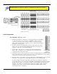
These indicated lines connect to
Source (+) and Source (-) lines of
the Lower Channel Circuit.
BCR stands for Bridge-Completion
Resistors.
Gain
Adjust
1
2
DC Coupling
AC
Bypass
Filter
5 mV
Address
Recog.
S1
DBK16 Block Dia
g
ram
A wide-range excitation regulator is adjustable from 1.5 to 10.5 VDC with a current limit of 50 mA. The
DBK16 requires a 12 to 15 VDC external excitation voltage that can be supplied from the DBK30A battery
module or other user-supplied source.
Hardware Setup
CAUTION
Each regulator has a maximum current of 50 mA. The maximum amount of
excitation that can be provided by the DBK16 excitation regulator is represented by
the following equation:
V
EXC[MAX]
= 0.05 × R
GAGE
Where R
GAGE
= the resistance of 1 element in the bridge circuit.
Exceeding the maximum allowed excitation can cause the DBK16 to fail.
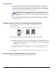
Card Connection
For DBK16s, the strain gage is configured as a 4-element bridge. There are 4 legs in a bridge circuit; the
quarter, half or full designation refers to how many elements in the bridge are strain-variable. A quarter
bridge has 1 strain-variable element; a half bridge has 2; and a full bridge has 4. Each DBK16 channel has
locations for bridge completion resistors. These resistors of fixed values are necessary to fill out the bridge
configuration.
In the following diagram, a 4-element bridge-type strain gage is referenced to the upper and lower channel
bridge completion resistor designations for the DBK16.
Bridge resistors are used in either the DBK16 or the strain gage,
but not in both at the same time.
DBK16, pg. 2 879895 DBK Option Cards and Modules