
User manual


DBK8 8-Channel High-Voltage Input Card
Overview …… 1
Hardware Setup …… 2
Card Configuration …… 2
Card Connection …… 2
CE Compliance …… 2
DaqBook/100 Series & /200 Series and DaqBoard [ISA type] Configuration …… 3
DaqBook/2000 Series & DaqBoard/2000 Series Configuration …… 3
Daq Device Connection …… 3
Safe Mounting …… 3
Software Setup …… 3
DBK8 – Specifications …… 4
Reference Notes:
o Chapter 2 includes pinouts for P1, P2, P3, and P4. Refer to pinouts applicable to your
system, as needed.
o In regard to calculating system power requirements, refer to DBK Basics located near
the front of this manual.
Note:
DBK8 has a footprint for installing a second DB37 connector, to accommodate input signals.
Pins 30 to 37 correspond to channels 7 to 0; pins 11 to 18 correspond to channels 15 to 8
(or low 7 to 0 in differential mode). This pinout [for the footprint] is the same as P1 for the 16 main
channels, with exception that the non-channel pins are not wired. Chapter 2 includes P1 pinouts.
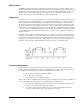
Overview
The DBK8 reads voltages up to ±100 V from DC to 10 kHz. The inputs are balanced differential and
referenced to the LogBook or the Daq Device analog common. No external biasing resistors are used. The
input impedance of each DBK8 channel is 10 MΩ to minimize loading of the circuit being measured. Two
DBK8s can share the same base channel to allow a maximum of 32 DBK8s and 256 high-voltage inputs.
DBK Option Cards and Modules 888194 DBK8, pg. 1