
User manual


Edge Selection
The DBK7 determines the frequency by measuring the time between successive rising or falling edges of
the input signal. Which edge is electrically cleaner depends on the application and related components. If
rising edges are used, the edge-selection circuit does not modify the signal. If falling edges are used, the
circuit inverts the signal so falling edges appear as rising edges to the subsequent circuits. Through
software, each channel can be independently set for rising- or falling-edge.
Debouncing
Debouncing is a process of ignoring signals too short to be real events. When a relay or switch closes, the
electrical contacts may not initially make good contact. Mechanical vibrations can occur, and contact is
made and broken several times stabilizing. Counting all these signals would yield too high a frequency.
The debounce circuit solves this problem by ignoring rising edges not preceded by a sustained low signal.
The sustain interval can be set in software to 0, 0.6, 2.5, or 10 ms for each channel. Debouncing may be
disabled (0 ms) for clean, high-frequency signals. Long debounce times will limit high-frequency response
(e.g., a 10 ms debounce will limit the frequency to about 100 Hz). In general, use “0” (debounce disabled)
for clean, high-frequency signals; increase the debounce as needed for noisy, low-frequency signals from
switches and relays.
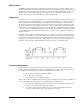
The figure shows the effect of 10 ms debouncing on a noisy signal. To be counted, a rising edge must be
preceded by a low sustained for at least 10 ms without any other edges. Rising edges a and f are counted
because they are preceded by low signal levels sustained for at least 10 ms (the debounce time). All other
rising edges (b, c, d, and e) are ignored. Any falling edge makes (or keeps) the debounced output low,
regardless of preceding edges. Thus, the DBK7 can detect short pulses even with debouncing.
Frequency Measurement
After debouncing, the signal’s frequency is ready to be measured. Frequencies are measured to 12-bit
accuracy between a minimum frequency (F
min
) and maximum frequency (F
max
). This frequency range can
be programmed individually for each channel. The limitations on F
min
and F
max
are:
• The frequency range must be within 0 to 1 MHz.
• F
max
- F
min
must be at least 1 Hz.
• F
max
/ F
min
must be at least 100/99 (1.010101).
Based on F
min
and F
max
, the DBK7 measures the frequency by counting input cycles during a variable time
interval. The length of the interval depends on the difference between F
min
and F
max
.
• For a wide range (when F
min
and F
max
are far apart), each bit of the 12-bit result represents a
large frequency change and can be measured quickly.
• For a narrow range (when F
min
and F
max
are close together), each bit of the 12-bit result
represents a small frequency change and takes longer to measure.
DBK Option Cards and Modules 879895 DBK7, pg. 11