
User manual


2. Place the JP2 jumper in the SSH position (See previous CAUTION).
3. For DaqBook/100, /112 and /120 only, place JP3 jumpers in bipolar mode.
4. For DaqBook/100, /112 and /120 only, place JP4 jumpers in single-ended mode.
DaqBook/2000 Series & DaqBoard/2000 Series
No jumper configurations are required for these /2000 series devices.
Software Setup
Reference Notes:
o DaqView users - Refer to chapter 2, DBK Setup in DaqView.
o LogView users - Refer to the chapter 3, DBK Setup in LogView.
Hardware Function
This section explains DBK7 functions that affect user settings to ensure the best performance. For setup
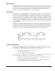
questions or noise problems, refer to the related section. The figure provides an overview of signal
conditioning function blocks and can be referred to for the following discussions.
Input Signal Conditioning
The DBK7 conditions the input signal in several ways to provide the best output accuracy. Reducing noise
and limiting the bandwidth are the first steps in the conditioning process and are done in hardware.
Software can further clean up the signal by selecting the cleanest edge to read and by setting a debounce
delay to ignore spurious signals.
Analog Input Signal Conditioning
The equivalent analog input circuit is shown in the figure. Input voltages should be at least 50 mV peak-
to-peak. The maximum analog input signal is 30 Vrms (42 Vpeak, 84 Vp-p). Stronger signals may
damage the DBK7 or present an electrical shock hazard.
When the input circuit jumpers are set for analog, the center conductor of the BNC connector is AC-
coupled through a 0.33 µF capacitor to the attenuator. The outside conductor connects directly to ground.
With the attenuator disabled for full sensitivity, input-protection diodes limit the signal to about 1.5 Vp-p.
Larger signals will see an impedance of 6.7 KΩ (rather than 20 KΩ) in series with 0.33 µF. With the
attenuator enabled, the input impedance remains 20 KΩ regardless of the input level.
After AC-coupling, attenuation and filtering, a comparator converts the input signal into a clean digital
signal. The comparator output is high when the center-pin signal is higher than the outside-conductor
signal (and low when the center-pin is lower). The comparator has hysteresis to reduce the effects of noise
by ignoring small signals.
DBK Option Cards and Modules 879895 DBK7, pg. 9