
User manual


DBK5 4-Channel Current Output Card
Overview …… 1
Hardware Setup ……. 2
Card Configuration ……. 2
Card Connection ……. 3
CE Compliance ……. 3
Software Setup ……. 4
DBK5 – Specifications ……. 4
This product is not used for LogBook applications.
Reference Notes:
o Chapter 2 includes pinouts for P1, P2, P3, and P4. Refer to pinouts applicable to your
system, as needed.
o In regard to calculating system power requirements refer to DBK Basics located near the
front of this manual.
Overview
DBK5 Block Diagram
The DBK5 can control four 4 to 20 mA current loops. The card connects to the Daq Device’s P1 port and
uses one of the Daq Device’s 16 base channels. Up to four DBK5s can share a single base channel for a
maximum of 256 channels. The DBK5 card neither sources nor sinks current; instead, it modulates current
in an externally powered loop. In this way, the DBK5 acts as a current-loop transmitter. The DBK5 is
compatible with both regulated and unregulated loop supplies, providing these supplies are within the
range of 12 to 45 V and have a loop resistance that does not exceed 1.95 kΩ, according to the following
relationship:
V
SUPPLY
= V
TRANSMITTER
+ (I
LOOP
* R
LOOP
)
where: V
TRANSMITTER
= 6 V, and I
LOOP
= 20 mA max
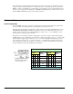
DAC mA
0 4
... ...
1000 7.9
... ...
4095 20
The DBK5 provides loop-current control through 12-bit digital-to-analog converters
(DACs). The 12-bit range of 0 to 4095 corresponds with 0 to 100% of full-span and an
output of 4 to 20 mA. As shown in the table, the current output I
OUT
= 4 mA +
(DAC/4095 × 16 mA). Thus, the DAC values for currents between 4 and 20 mA is
equal to 255.94 × (I
OUT
- 4 mA).
DBK Option Cards and Modules 879895 DBK5, pg. 1