
User manual


Accelerometer Tutorial
This accelerometer tutorial covers the following topics. Page numbers refer to DBK4 document module
pages.
What is a Piezoelectric Accelerometer?......11
Accelerometer Specification Parameters......11
Physical Setup......13
Electrical Grounding......14
Practical Limitations...... 15
Cable-Connector Handling Precautions......15
Cable Driving......16
What is a Piezoelectric Accelerometer?
A low-impedance piezoelectric accelerometer consists of a piezoelectric crystal and an electronic amplifier.
When stretched or compressed, the two crystal surfaces develop a charge variation that is related to the
amount of stress, shock, or vibration affecting the crystal. The amplifier outputs a corresponding signal
and transforms the sensor’s high impedance to a lower output impedance of a few hundred ohms. Besides
acceleration, such sensors can measure pressure and force.
The circuit requires only 2 wires (coaxial or twisted pair) to transmit both power and signal. At low
impedance, the system is insensitive to external or “triboelectric” cable noise. Cable length does not affect
sensitivity.
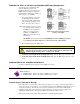
The figure shows a simple sensor-DBK4 connection. The MOSFET is powered from a constant-current
source of 2 or 4 mA at 27 volts. In the quiet state, the MOSFET circuit will bias off at about 12 V. As the
system is excited, a voltage develops across R and the crystal and is applied to the gate of the MOSFET.
This voltage will cause linear variation in the impedance of the MOSFET and a proportional change in bias
voltage. This voltage change will be coupled to the DBK4 input amplifier through the capacitor C. The
value of R and the internal capacitance of the crystal control the low-frequency corner. Units weighing
only a few grams can provide high-level outputs up to 1 V/g with response to frequencies below 1 Hz.
Accelerometer Specification Parameters
Noise in Accelerometers
The noise floor or resolution specifies the lowest discernible amplitude (minimum “g”) that can be
measured. There are two main sources of noise:
• Noise from the crystal and circuit inside the accelerometer. Some types of crystals, such as
quartz, are inherently more noisy than others. A good noise floor is 10 to 20 µV.
• Noise from electrical activity on the mounting surface. Since the signal is a voltage, 60 Hz or
other voltages (induced or ground loop, etc) may interfere. The best protection is to
electrically isolate the accelerometer.
DBK Option Cards and Modules 958293 DBK4, pg. 11