
User manual


DBK Option Cards and Modules 958293 DBK4, pg. 9
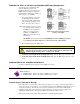
Software Controls
Power management, the PGA, and the low-pass filter’s cut-off frequency are all software controllable.
These parameters are sent via the external address bus in the P1 connector to the DBK4. The micro-
controller decodes the configuration message, sets the PGA and filter controls, and illuminates the on-
board LED. However, if transmission errors are detected, the micro-controller flashes the LED and ignores
the message. The error is cleared when an error-free message is received. At power up, the current source
and filters are powered off and the LED is off. The LED will remain off until the DBK4 is successfully
addressed for the first time.
DBK4 – Specifications
Name/Function: 2-Channel Dynamic Signal Input Card
Physical Specifications
Channels: 2
Signal Connection: 1 BNC connector per channel
Dimensions: 8.28" W × 3.25" H
Operating Specifications
Power Consumption (typical): 20 mA @ +5 V, 95 mA @ +15 V, 80 mA @ -15 V
Current Source:
Output Impedance: >1.4 MΩ
Compliance: 27 VDC
Current Levels: 2 & 4 mA
Broadband Noise: 0.3 µA RMS (Bw = 100 kHz)
Input Impedance: 150 kΩ
Gain:
Bypass Mode: ×1.583 ×15.83 ×158.3
Filter Mode: ×1 ×10 ×100
Input Ranges: ±5 V ±500 mV ±50 mV FS
Coupling: AC, DC
AC: 1-pole, 10 Hz HPF
1-pole, 0.1 Hz HPF
Input Signal/Noise: >96 dB (Bw = 100 kHz)
Filter(Typical):
Distortion (typical)
Bypass Mode: The jumpers JP7 and JP8 in the 1-2 position disabling
the programmable low pass filter.
@ 100 Hz - 81 dB
@ 1 kHz - 82 dB
@ 5 kHz - 81 dB
Filter Mode: The jumpers JP7 and JP8 in the 2-3 position enabling the
programmable low pass filter. With the following cutoff
frequencies selected via software.
4.5 kHz cutoff frequency:
@ 100 Hz - 79 dB
@ 1 KHz - 75 dB
18 kHz cutoff frequency:
@ 100 Hz - 68 dB
@ 1 KHz - 68 dB
@ 5 kHz - 58 dB
*Note the filter mode measurements were taken at the +5 V range
with the software enabled switched capacitor clock and excitation.