
User manual
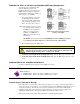


Signal Coupling
The input can be configured via jumpers to maximize the usable signal spectrum. The DBK4 provides
two, 1-pole High-Pass Filters (HPF) and one DC path. The HPF can be set to 0.1 Hz, 3 dB cut-off
frequency. In this case, the system frequency response is limited by the source characteristics. The HPF
can also be set to 10 Hz, 3-dB cut off frequency, for high-frequency measurements. The 10 Hz setting is
useful in attenuating setup-induced low-frequency signals that can reduce the dynamic range (e.g., when
using tape recorders as signal sources).
Note: When using 0.1 Hz coupling, you should set the baseline (via software) to one-shot mode.
The DC path allows the DBK4 to be used in voltage-mode measurements that convey DC as well as AC
information. For example, when motion is measured with a DC LVDT, the transducer is biased with an
independent power supply and its output is referenced to ground.
CAUTION
JP4 or JP5, as applicable, must be removed to disable the current source whenever the
input is DC-coupled. Failure to remove JP4 or JP5, when the input is DC-coupled, can
result in transducer damage.
Amplifier
The DBK 4 includes a Programmable Gain Amplifier (PGA) with three gain settings (×1, ×10, and ×100).
The gain settings are set for each channel via software. These gain settings are performed at configuration
and remain unchanged during a measurement sequence. The PGA has a flat response up to 100 kHz for
in-band and out-of-band frequencies.
Low-Pass Filter
To protect the in-band components from distortion caused by aliases of the out-of-band spectrum, the
DBK4 features a 12-pole programmable Butterworth Low-Pass Filter (BLPF). There are eight 3 dB cut-off
frequency (Fc) settings per channel, the lowest frequency is 141.6 Hz and the highest is 18 kHz. In
general, high order BLPF introduce amplitude and phase distortion near the 3 dB cut off frequency.
Limiting the measurement range can reduce this error. A typical measurement range is 70% to 80% of the
3-dB cut-off frequency.
For narrowband measurements, the anti-alias filter can be bypassed providing an extended bandwidth of
40 kHz. In this configuration, the channel has lower distortion and a gain factor of 1.583. This setup may
be useful when calibrating accelerometers with sinusoidal motion. However, in this case, special attention
should be given to external noise since high-frequency noise will be aliased into the signal band.
The switched capacitor clock must be turned on in software for the filter to work.
Sample and Hold
The card’s sample and hold amplifier samples all channels within a system (up to 256) within 50 ns of one
another and preserves their phase information. Measurement of transmissibility can be made between any
two of the 256 possible channels.
The Simultaneous Sample and Hold (SSH) is triggered on the first channel of a scan sequence; after which,
the A/D converter sequentially measures the output of each of the SSH amplifiers. In a scan sequence, the
first channel should be a non-SSH channel. However, if the scan sequence contains only SSH channels the
first channel will contain data taken in the sample mode. This data is inaccurate and therefore should be
discarded; however, the second sample (valid) can be a repeat of the first.
Power Management
The DBK4 has circuits for a variety of measurement environments. When not needed, the filters and/or
current source can be powered down via software. This feature can be useful in field units to reduce
overall power consumption.
DBK4, pg. 8 958293 DBK Option Cards and Modules