
User manual


DBK1 16-Connector BNC Adapter Module
Overview …… 1
Hardware Setup …… 2
DBK1 Configuration …… 2
JP4 Configuration in DaqBook …… 2
Software Configuration …… 2
DBK1 – Specifications …… 2
Reference Notes:
o Chapter 2 includes pinouts for P1, P2, P3, and P4. Refer to pinouts applicable to your
system, as needed.
o In regard to calculating system power requirements, refer to DBK Basics located near
the front of this manual.
Overview
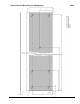
The DBK1 provides a convenient means of attaching analog input signals from BNC cables to a LogBook
or Daq Device via the P1 interface. Each of the 16 inputs has a switchable 100 KΩ bias resistor to
accommodate floating signal sources. The 16 inputs can be used as 16 single-ended inputs (channel 0 to
15) or as 8 differential pairs (channel 0 to 7). The BNC inputs are grouped to reflect use in the differential
mode (ch 0, ch 8, ch 1, ch 9, ch 2, ch 10 ...) where channel 8 serves as the low-signal line of channel 0 and
so forth.
DBK Expansion Options 886995 DBK1, pg. 1