
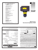
- Omega Engineering, Inc. Non-Intrusive Capacitance Switch User's Guide

Step Eight Step Nine
CALIBRATION CALIBRATION
After it is installed in place, the LVP-51 series must be calibrated by the
user before operation. Everything needed for the procedure is self-con-
tained within the electronics of the LVP-51 series level switch. Two
dielectric states—full condition and empty condition—are measured by
the LVP-51 series, and then averaged to set the threshold between
“wet” and “dry” at the sensor. The empty state must be at least 6"
below the bottom of the sensor for calibration. The full state must be
to the top of the sensor (not just to the point of actuation) for calibra-
tion. The actual application fluid at its intended operating temperature
must be used during calibration. Use the following procedure assumes
that the sensor has already been wired to a power supply.
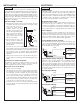
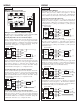
1. Remove the cap from the sensor body by loosening the two
screws located below the sensor. Do not remove the screws from
the sensor. Insert a small screwdriver into the small slot at the
edge of the cap and gently pry upwards.
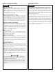
2. Looking down you will see a small three-position switch and two
trimpots marked Full and Empty. You may start with whatever
state the tank is in.
3. Full state: With
the tank filled to
the top of the sen-
sor, set the switch
to the Full posi-
tion (right). Make
sure your hands or
any other objects
are not touching
the sensor while calibrating because this will cause a false read-
ing. Using a small nonmetallic screwdriver or alignment tool, turn
trimpot Full until the LED just lights, and no farther. Note the
position. Now turn the trimpot back until the LED turns off. The
ideal setting for the trimpot is midway between these on and off
points.
4. Empty state: With the tank drained to a point no closer than 6
inches below the bottom of the sensor, set the switch to the Empty
position (left). Set the Empty trimpot as in Step 3.
5. After completing calibration, make sure to return the switch to the
center position. Snap the cap back on by pressing down, and tight-
en the two screws.
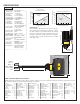
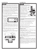
Checking the Point of Actuation:
Raise the fluid level to the point
where the sensor sends a “wet”
signal (Input LED will turn
Amber on Omega controllers).
The “dry” signal should be
sent when the fluid level is
lowered (Input LED will turn
Green on Omega controllers).
The actual Point of Actuation
(POA) depends on many variables,
including the thickness of the wall and
the dielectric value of the liquid. For
example, thicker tank walls can
raise the POA while thinner
walls could lower the POA.
If the POA needs to be
changed, measure the distance and remount the
sensor in a new location.
Do not attempt to change the Point of Actuation by intentional
miscalibration.
If the sensor does not signal wet and dry reliably, it may be that:
• the dielectric constant of the application fluid is too low
• the tank wall is too thick for the application fluid
• there are static or other electrical charges in the fluid
• metal objects are within 6" of the sensor
• calibration was performed incorrectly
Try the calibration procedure again, after making corrections if possi-
ble. If the full and empty states are too similar dielectrically, it may
not be possible to use a capacitance sensor.
Testing the Sensor:
1. Power: Apply power to sensor, by connecting power to the con-
troller and/or power supply.
2. Full condition: Fill the tank with the application liquid, by filling
the tank up to the sensor’s point of actuation.
3. Test: With the sensor being fluctuated between wet and dry states,
use a multimeter to ensure that the correct signals are being pro-
duced by the LVP-51 series level switch, or observe the sensor
indicator light in the controller.
4. Point of Actuation: Observe the point at which the rising or
falling fluid level causes the sensor to change state, and move the
installation of the sensor if necessary.
Maintenance:
The LVP-51 series level switch itself requires no periodic mainte-
nance except cleaning as required. However, periodically clean any
coating or scaling on the tank wall the sensor is attached to and check
the calibration. It is the responsibility of the user to determine the
appropriate maintenance schedule, based on the specific characteris-
tics of the application liquids. In addition, any dripping or condensa-
tion between the sensor and the tank wall fitting may need to be peri-
odically cleaned to maintain accuracy.
FULLEMPTY
CAL CAL
EMPTY OPERATE FULL
LED
Full PotEmpty Pot
Switch
Screw Housings
LED
Full
Pot
Empty
Pot
Switch
Screws
Empty
Cal
Full
Cal
Operate
Point of
Actuation
(POA)
Full
Calibration
Point
Empty
Calibration
Point
6"
min.
1"
max.
Non-conductive
plastic tank wall