
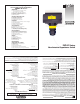
- Omega Engineering, Inc. Non-Intrusive Capacitance Switch User's Guide

Step Four Step Five
INSTALLATION ELECTRICAL
OMEGA's LVP-51 series level switch may be installed anywhere on
a tank wall using the supplied PE fitting that the switch slides into.
The fitting comes with adhesive on the tank side that is sufficient to
hold the sensor in position temporarily while the installation is tested,
but for permanent installation the fitting must be welded, glassed or
strapped to the tank. Extra fittings are available from Omega, so that
the level switch may be moved to different locations on the tank by
sliding it into other fittings.
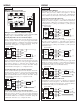
Attach the fitting to the tank:
1. Determine the mounting location for the level switch. The point
of actuation (where the sensor will send a “wet” signal) is most
often at the center of the sensor;
however the actual Point of
Actuation (POA) may differ
depending on the application liq-
uid and tank wall characteristics.
After positioning the fitting to
check clearances, etc., remove the
paper protective strips from the
adhesive of the fitting.
2. Press the fitting into place. The
adhesive provides a seal between
the sensor and the tank wall, and
will hold it in place during testing
and installation.
If desired, the sensor may be installed temporarily without weld-
ing the fitting to the wall. If several different locations must be
tried before permanent installation, use double-sided foam stick
tape designed for PE, for example Arclad type PE-6024,
CO#7331 (from Adhesive Research Inc., Glen Rock PA 17327) or
equivalent.
3. After the sensor has been tested to verify the POA, weld, glass or
strap the fitting to the tank using standard industrial plastic tech-
niques.
Special note for small round tanks:
The fitting may be attached to small, round tanks, as long as the
majority of the fitting is firmly attached to the wall. However,
extreme installations may effect the switches performance.
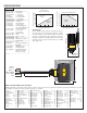
Mount the sensor in the fitting:
1. Slide the sensor into the fitting.
2. After trimming the sensor wire to length if needed by the installa-
tion, thread the sensor wire into a plastic flexible conduit with a
1/2" male fitting. Screw the conduit into the sensor, being careful
not to cross the threads. Do not over tighten the conduit in the
sensor as this may break the fitting. Such damage is not covered
by the warranty. Take care while pulling the wire through conduit
that no excessive tension is placed on the sensor end of the wire,
so that the wire is not broken from the sensor housing.
3. Connect the sensor wire to the controller following the instruc-
tions in its manual. See the following Wiring Section for detailed
wiring instructions.
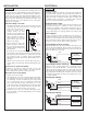
Signal Outputs (Relay switching):
Allows the sensor to switch a small load on or off directly, using an
internal 1 A relay (60 VAC/60 VDC). All models, LVP-51 series-
_005, use the relay and features 4 wires (red, black, white and green)
and a shield wire. The NO/NC status is set by the polarity of the volt-
age feeding the Red and Black wires. The Green wire is the common
for the relay and the White is the NO or NC, depending on the polar-
ity of Red and Black.
Normally Open Wiring:
Supply Voltage:
The supply voltage to the LVP-51 series level switch should never
exceed a maximum of 36 VDC. Omega controllers have a built-in 13.5
VDC power supply which provides power to all of OMEGA's electri-
cally powered sensors. Alternative controllers and power supplies, with
a minimum output of 12 VDC up to a maximum output of 36 VDC,
may also be used with the LVP-51 series level switch.
Required Cable Length:
Determine the length of cable required between the LVP-51 series
level switch and its point of termination. Allow enough slack to
ensure the easy installation, removal and/or maintenance of the sen-
sor. The cable length may be extended up to a maximum of 1000 feet,
using a well-insulated, 14 to 20 gauge shielded four conductor cable.
Wire Stripping:
Using a 10 gauge wire stripper, carefully remove the outer layer of
insulation from the last 1-1/4" of the sensor's cable. Unwrap and dis-
card the exposed foil shield from around the signal wires, leaving the
drain wire attached if desired. With a 20 gauge wire stripper, remove
the last 1/4" of the colored insulation from the signal wires.
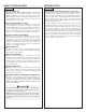
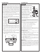
Signal Outputs (Current sensing):
The standard method used by Omega controllers; this technology uses
only two wires (Red and Black). The sensor draws 5 mAwhen it is dry,
and 19 mA when wet. NC/NO status must be set by the controller. The
Green and White wires are not used.
Red
Black
Shield
Ground
24 VDC
Power Supply
+
-
Multimeter
(mA)
-
+
Multimeter
(Continuity)
Red
Green
Shield
Ground
24 VDC
Power Supply
+
-
-
+
Black
White
Weld
Fitting
Sensor
1/2" NPT
Connector
Screw
Multimeter
(Continuity)
Black
Green
Shield
Ground
24 VDC
Power Supply
+
-
-
+
Red
White
Normally Open Wiring: