User's Guide http://www.omega.com e-mail: info @omega.
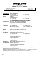
OMEGAnet On-Line Service http://www.omega.com Internet e-mail info@omega.com Servicing North America: USA : ISO 9001 Certified Canada : One Omega drive, Box 4047 Stamford, CT 06907-0047 Tel : (203) 359-1660 e-mail : info@omega.com 976 Bergar Laval (Quebec) H7L 5A1 Tel : (514) 856-6928 e-mail : info@omega.
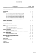
CONTENTS DESCRIPTION SECTION PAGE =========================================================================== IMPORTANT SAFETY CONSIDERATIONS 1 3 UNPACKING AND INSPECTION 2 4 MAIN FEATURES 3 5 MODELS 4 6 LDP-1X4-MX, TEMPERATURE INDICATOR FOR RTD SENSOR (PT-100) LDP-1X4-J1,J2 TEMPERATURE INDICATOR FOR THERMOCOUPLE "J" 6 6 LDP-1X4-K1,K2 TEMPERATURE INDICATOR FOR THERMOCOUPLE "K" 6 LDP-1X4-T1,T2 TEMPERATURE INDICATOR FOR THERMOCOUPLE "T" 6 LDP-1X4-E1,E2 TEMPERATURE INDICATOR FOR THERMOCOUPLE "E
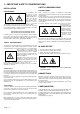
1.- IMPORTANT SAFETY CONSIDERATIONS INSTALLATION SAFETY CONSIDERATIONS PRESCRIPTIONS.- PRECAUTIONS.The installation and the future use of this unit must be done by suitable qualified personnel. The unit has not AC (mains) switch, it will be in operation as soon as power is connected. The installation must incorporate an external main switch.
2.- UNPACKING AND INSPECTION It is advisable to do a detailed reading of this Manual before mounting the instrument. This Operator's Manual contains all the technical specifications : electricals as well as mechanics, both necessary to do a correct installation and also a good use of the instrument. At the same time the user will acquire the knowledge needed to obtain the best performances of the product.
3.- MAIN FEATURES On this paragraph is detailed the main features for every one of the series which are the following : Instruments of four digits plus polarity (only minus) to show temperature using the signal generated by sensors type RTD (PT-100 (0.00385), model MX) or Thermocouples (models J1,J2, K1,K2, T1,T2, E1,E2, S1,S2, R1,R2 and L1).
4.- MODELS LDP-1X4-MX Temperature indicator for RTD sensor type PT-100 (100 Ω at 0 °C Alpha = 0.00385). This model uses the 3-wire measurement, which compensates thelead wire resistance. However 2-wire sensors can be used too. See wiring connections. The sensor signal is linearized according to IEC 751-DIN 43760. The maximum excitation current is @1 mA. LDP-1X4-J1,J2 Temperature indicator for thermocouple sensor type J (Fe-Kons).
5.- GENERAL SPECIFICATIONS DISPLAY ENVIRONMENTAL TYPE . . . . . . . . . . . . . . . . . . . . . . . . . 4 digits, 7 segments, red or green LED. HEIGHT DIGIT . . . . . . . . . . . . . . . . . . 57 mm. (2.3") or 100 mm. (4"). RANGE . . . . . . . . . . . . . . . . . . . . . . . -9999 a 9999 POLARITY . . . . . . . . . . . . . . . . . . . . . Minus only (-). OVERRANGE . . . . . . . . . . . . . . . . . . Display flashing. DECIMAL POINT . . . . . . . . . . . . . . . . Models M1& M3. OPERATING TEMPERATURE . .
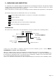
8.- WIRING 8.1.- POWER SUPPLY, RECOMMENDED WIRING POWER SUPPLY 115 Vac (230 Vac Optional). Power switch FUSE and spare fuse. 8.2.- PROTECTION FUSES The unit has a protection fuse located on the power supply socket. If this fuse must be replaced or changed because the power supply is changed, use the time-lag fuse according to IEC 127/2 with the values indicated on the table. Power Supply Fuse value 230 Vac 115 Vac 0.2 A 0.4 A 8.3.- SENSOR CONNECTIONS FOR MODEL: MX.
9.- TEMPERATURE RANGES 9.1.- MODEL M1, M2 & M3. RTD SENSOR (PT-100) MODEL TEMPERATURE RANGE ACCURACY (±1 COUNT) RESOLUTION 0.1 °C M1 - 100.0 to + 650.0 °C ± 0.4 % M2 -300 to 1526 °F ± 0.4 % 1 °F M3 - 200.0 to 999.9 °F ± 0.2 % 0.1 °F MAXIMUM COMPENSATION 10 Ω Allowable error in negative range due to the lead wire resistance : 0.2°C/Ω or 0.4°F/Ω 9.2.- MODELS: J1,J2,K1,K2,T1,T2, E1,E2,S1,S2,R1,R2 & L1.
.- ADJUSTMENT AND CALIBRATION PROCEDURE 11.1.- RTD MODELS A decade box or RTD simulator is required. 1.- Check that the instrument is not powered. 2.- Connect the RTD simulator or decade box to the signal input connector (See paragraph 8.3). 3.- Remove the rear cover taking off all the screws to obtain access to the control board. (See page 7 paragraph 7). 4.- Power up the instrument with the appropriate power supply and wait until 3 minutes before to start the adjust. 5.
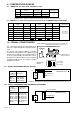
.- INSTALLATION 1.- Prepare a panel cut-out with the dimensions indicated on paragraph 13. 2.- Slide the instrument (1) into the cut-out. 3.- Slide the two fixation pieces (3) with T shape by both lateral sides of the instrument, such as it is shown on the drawing below. 4.- Turn the screw bolt until it is pressed firmly against the panel (4) and the instrument (1) remains totally fixed. 5.- The front part of the instrument has the necessary elements to provide an IP 65 protection.
WARRANTY/DISCLAIMER OMEGA ENGINEERING, INC. warrants this unit to be free of defects in materials and workmanship for a period of 13 months from date of purchase. OMEGA warranty adds an additional one (1) month grace period to the normal one (1) year product warranty to cover handling and shipping time. This ensures that OMEGA’s customers receive maximum coverage on each product. If the unit malfunction, it must be returned to the factory for evaluation.
Where Do I Find Everything I Need for Process Measurement and Control? OMEGA...