User’s Guide http://www.omega.com e-mail: info@omega.
omega.com TM ® OMEGA OMEGAnetSM On-Line Service http://www.omega.com USA: ISO 9001 Certified One Omega Drive, Box 4047 Stamford, CT 06907-0047 Tel: (203) 359-1660 FAX: (203) 359-7700 e-mail: info@omega.com USA and Canada: Mexico and Latin America: Benelux: Czech Republic: France: Germany/Austria: United Kingdom: ISO 9002 Certified Internet e-mail info@omega.com Canada: 976 Bergar Laval (Quebec) H7L 5A1 Tel: (514) 856-6928 FAX: (514) 856-6886 e-mail: canada@omega.
Contents 1. GENERAL DESCRIPTION 2. MOUNTING INSTRUCTIONS 3. REPLACING FUSES 4. ASSEMBLY 5. CURRENT INPUTS 6. CONNECTING TRANSMITTERS TO THE MULTIPLEXER 7. CONNECTING Pt-100 TO THE MULTIPLEXER 8. CONNECTING THE MULTIPLEXER TO A PLC 9. CONTROL 9.1 Enable 9.2 Address 9.3 Address Polarity 9.4 Control Tables 10. CALIBRATION 10.1 Calibration Procedure 10.2 Calibration Tables 10.2.1 "ZERO" - Coarse Calibration Tables 10.2.2 "SPAN" - Coarse Calibration Tables 11. MULTIDROP CONFIGURATION 12.
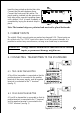
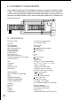
1. GENERAL DESCRIPTION The DRA-RTM-8 is a multiplexer for 16 analog inputs - eight of which, marked 1-8, are direct inputs for Pt-100 sensors, while the remaining (9-16), are for 420mA current loops. The DRA-RTM-8 output format is a 4-20mA current loop, with a 28mA limitation. Each Pt-100 input has its own signal conditioner, allowing each input to be calibrated separately. Each signal conditioner includes six DIP switches for coarse calibration and two potentiometers for fine tuning. 2.
Insert the two printed cards into their slots. Connect the flat cable between them. Connect the front panel flat cables. The panel must be inserted into the grooves on both sides of the case while pressing down until a distinct "click" is heard. Assembly is completed by laying the terminal strips in place. Figure 1. Note: The terminal strips are polarized and must not be placed backwards. 5. CURRENT INPUTS The eight 4-20mA current inputs are marked as channels 9-16. These inputs are for current only.
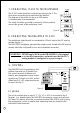
7. CONNECTING Pt-100 TO THE MULTIPLEXER The Pt-100 probe should be connected according to fig 4. The three wires connecting the probe should be identical. The distance of the probe can be up to 200 meters. A shielded cable is recommended. The shield should be grounded at one point. When possible, connect the ground at the multiplexer's end. Figure 4. 8. CONNECTING THE DRA-RTM-8 TO A PLC The multiplexer output should be connected to 4-20mA input of the PLC analog module (see fig 5).
9.2 ADDRESS The required channel is selected by four address lines. The operating voltages are: Logical "1" 5V < Vi < 60V Logical "0" 0V < Vi< 0.5V 9.3 ADDRESS POLARITY (see fig 6) Figure 6. Address polarity is controlled by three internal pins and a jumper over two of them, located on PN 7021 printed circuit board, accessible behind the Enable terminal. The unit is supplied with the jumper set for "true high" control logic, i.e. "0000" selects channel #1, and "1111" selects channel #16.
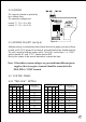
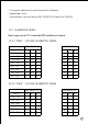
9.4.2 "TRUE HIGH" SETTING ADDRESS BUS A3 A2 A1 A0 0 0 0 0 0 0 0 1 0 0 1 0 0 0 1 1 0 1 0 0 0 1 0 1 0 1 1 0 0 1 1 1 x x x x E/T OUTPUT CHANNEL 1 1 1 1 1 1 1 1 0 1 2 3 4 5 6 7 8 TEST MODE ADDRESS BUS A3 A2 A1 A0 1 0 0 0 1 0 0 1 1 0 1 0 1 0 1 1 1 1 0 0 1 1 0 1 1 1 1 0 1 1 1 1 x x x x E/T OUTPUT CHANNEL 1 1 1 1 1 1 1 1 0 9 10 11 12 13 14 15 16 TEST MODE Note: The unit includes three internal potentiometers. These potentiometers are carefully adjusted and sealed in the factory.
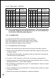
i. Change the address to the next channel to be calibrated. j. Repeat steps b to h * The calibrator is set according to DIN 43760 Pt-100 table (a = 0.00385) 10.2 CALIBRATION TABLES Note: Logic state of "0" is when the DIP switch lever is down. 10.2.1 "ZERO" - COARSE CALIBRATION TABLES ZERO TEMP C O CHANNELS 1-4 CHANNELS 5-8 SW6 SW5 SW4 SW1 SW2 SW3 1 1 1 -50.....10 1 1 1 8.....75 0 1 1 0 1 1 74...140 1 0 1 1 0 1 139...206 0 0 1 0 0 1 205...272 1 1 0 1 1 0 270...
11. MULTIDROP CONFIGURATION In the disabled state (E=0), the multiplexer outputs no current and exhibits a high Z state. This mode allows the connection of several DRA-RTM-8 units to one PLC's analog input, by tying their output terminals and the address lines in parallel, and applying individual Enable lines to select the desired multiplexer by disabling all but one (see fig 7). ANALOG + ANALOG - PLC ANALOG INPUT MODULE ENABLE 1 ENABLE 2 MSB LSB DISCRETE OUTPUT MODULE Figure 7. 12.
WARRANTY/DISCLAIMER OMEGA ENGINEERING, INC. warrants this unit to be free of defects in materials and workmanship for a period of 13 months from date of purchase. OMEGA Warranty adds an additional one (1) month grace period to the normal one (1) year product warranty to cover handling and shipping time. This ensures that OMEGA’s customers receive maximum coverage on each product. If the unit should malfunction, it must be returned to the factory for evaluation.
Where Do I Find Everything I Need for Process Measurement and Control? OMEGA…Of Course! TEMPERATURE ⻬ Thermocouple, RTD & Thermistor Probes, Connectors, Panels & Assemblies ⻬ Wire: Thermocouple, RTD & Thermistor ⻬ Calibrators & Ice Point References ⻬ Recorders, Controllers & Process Monitors ⻬ Infrared Pyrometers PRESSURE, STRAIN AND FORCE ⻬ ⻬ ⻬ ⻬ Transducers & Strain Gauges Load Cells & Pressure Gauges Displacement Transducers Instrumentation & Accessories FLOW/LEVEL ⻬ ⻬ ⻬ ⻬ Rotameters, Gas Mass Flowm