MADE IN User’s Guide Shop online at www.omega.com e-mail: info@omega.com For latest product manuals: omegamanual.
OMEGAne OMEGAnett ® On-Line Service http://www.omega.com Internet e-mail info@omega.com Servicing North America: USA: ISO 9001 Certified Canada: One Omega Drive, Box 4047 Stamford, CT 06907-0047 Tel: (203) 359-1660 e-mail: info@omega.com 976 Bergar Laval (Quebec) H7L 5A1 Tel: (514) 856-6928 e-mail: info@omega.
1.0 TABLE OF CONTENTS: 1.0 Table of Contents:........................................................... i Warning and Safety Notice.................................................... v 2.0 Overview ......................................................................... 1 2.1 General Description ............................................................................................... 1 2.2 System Overview ...........................................................................................
Section 1.0 Table of Contents 3.1.4 Equipment Return ........................................................................................................................... 13 3.1.5 Storage ........................................................................................................................................... 13 3.2 Environment and Location .................................................................................. 13 3.3 Installation ...................................
Section 1.0 Table of Contents 4.9 Timer/Totalizer Reset ........................................................................................... 31 4.10 Special Events ...................................................................................................... 31 4.10.1 Record on Alarm ............................................................................................................................. 31 4.10.2 Record on External Event ..............................................
Section 1.0 Table of Contents 5.3.2 5.4 Bar Graphs ..................................................................................................................................... 54 5.3.2.1 Bar Graph Setup .................................................................................................................................................. 54 5.3.2.2 Trend Setup ............................................................................................................................
Section 1.0 Table of Contents 5.7.11 Languages ...................................................................................................................................... 79 5.7.12 System ReFlash ............................................................................................................................. 79 6.0 Communication ............................................................ 81 6.1 World Wide Web ........................................................................
Warnings and Safety Precautions NOTE The contents of this manual are correct at the time of issue. The contents may change at any time without prior notification. This is due to continuous developments to the recorder and its functionality. Trademarks Microsoft, MS-DOS, Windows, Windows 2000, Windows XP and Windows CE are all registered trademarks of Microsoft Corporation. CompactFlash™ and CF (logo) are trademarks of the Compact Flash Association (CFA).
Warnings and Safety Precautions WARNING AND SAFETY NOTICE This Safety Notice has been included to emphasize the DANGER OF HAZARDOUS VOLTAGES on the REAR TERMINAL PANEL of your instrument. USE EXTREME CAUTION WHEN INSTALLING OR SERVICING your instrument. Please read the entire contents of Section 2 - Installation and Wiring within this manual before attempting to install or service your instrument. 1.
Section 2 - Overview 2.0 OVERVIEW This manual applies to Firmware version 1.0 and above. This section gives a system overview of the recorder and the basic elements involved. 2.1 General Description The recorder is an 18 channel unit capable of measuring 6 or 12 live inputs which can be a combination of linear inputs – voltage or current, thermocouples, RTDs, or Frequency.
Section 2 - Overview System Overview Refer to the figure below: RELAY OUTPUTS DIGITAL INPUTS MASTER ENABLE ALARM EVENT MANAGER DISPLAY & KEYBOARD MANAGER ALARM MASTER SETUP DIGITAL OUTPUT SETUP ALARM EVENT LOG DISPLAY BUILDER ROTATE LIST WIDGET CONTROL SYSTEM MANAGER DIGITAL INPUT MANAGER MASTER ENABLE ETHERNET SYSTEM SECURITY SYSTEM SETUP LANGUAGE … ..
Section 2 - Overview The Data Manager is also controls the Analog Inputs calibration process. This is a privileged operation and allows an administrator to recalibrate the conversion factors and offsets on the various inputs and their associated ranges. All units are shipped fully calibrated with a default set of calibration parameters stored in non-volatile memory which may be recalled at any time. The Data Storage Manager is used to set up the recording parameters required by the user.
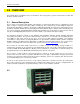
Section 2 - Overview 2.3 Recorder Front Figure 2-2 shows the front view of the recorder. The recorder has a ¼ VGA color display with touch screen. Below the display are a lockable media door, status indicator, IR COMM port and stylus used for data entry on the display. The recorder is intended to be panel mounted and if mounted correctly using the supplied gasket, the unit is waterproof to IP65 when the media door is closed and the waterproof lock cover is in place.
Section 2 - Overview 2.3.2 Media Door The media door is opened by turning the key in the lock ¼ turn clockwise and pulling the door out and down. Note that in order to meet the water resistance specification (IP65) the door must be closed and locked and the waterproof lock cover must be snapped over the lock. Opening the media door exposes the compact flash card socket and the USB port.
Section 2 - Overview 2.
Section 2 - Overview have an isolated frequency inputs which allows the unit to measure frequency to 10,000 Hz. Between the terminal blocks is the ambient temperature sensor for thermocouple compensation. 2.4.3 Input/Output Module The input/output module is optional and provides potential free relay contacts and isolated digital inputs. 2.4.4 Computer Interface The bottom of the rear panel is the computer interface. At the bottom right hand corner is a small cover secured by a screw.
Section 2 - Overview 2.5 Files 2.5.1 Configuration Files The recorder has hundreds of options and settings that need to be set up by the user. Things like input types, point tags, displays, record information and so-on. Once set up, this information is saved in the internal memory (SD Card) as a user named configuration file in a special directory called ConfigFiles. Each unique configuration is stored in a sub-folder within the ConfigFiles directory.
Section 2 - Overview Eg: To copy the “pumphouse” configuration to a different media you need to go to the ConfigFiles directory and copy the FOLDER “pumphouse_cfg”. In the root of the internal memory (SD card) are two files – config.xml and displays.xml. These are the default configuration files used by the system. When you quick-save a configuration, this is where it saves to. You should not transport these files but rather save the configuration as mentioned above. 2.5.
Section 2 - Overview 2.7 QUICK START GUIDE The recorder ships in a fully functional mode, but may not be set up the way you would want to use it and needs to be configured before it is used. There are several areas that need to be configured to customize the unit to the user‟s needs. This unique combination of settings is referred to as the system configuration and is saved in a file called the configuration file which is physically named config.xml.
Section 2 - Overview 2.8 Keyboarding While it is possible to connect a standard keyboard and mouse to the recorder, one may not be readily available in which case data is entered using the pop-up keyboard as shown right. When you enter a recorder setup screen where it is necessary to type in data, the instant you tap the input field box the keyboard pops up. Entry is made by tapping the keys firmly with the stylus. As each key is pressed it inverts its color.
Section 2 - Overview 2.11.1 User Levels There are three user levels for gaining direct access to the recorder. User levels are only active if security is enabled. The three levels are Administrator: Has access to all levels of the recorder menus and systems. Manager: Has restricted access. A Manager cannot set up any base level parameters, but can use existing setups to create alarms, displays and the like. User: Can use the recorder only as set up by the Administrator or Manager.
Section 3 – Installation 3.0 INSTALLATION This section provides information and procedures on installing and wiring the recorder. Included are handling procedures, installation and wiring specifications, and instructions for both standard and optional equipment. 3.1 Equipment Handling 3.1.1 Initial Inspection Exercise care when unpacking the instrument from the shipping carton. The instrument is packed in a shockproof foam retainer to prevent damage during normal transit.
Section 3 – Installation NOTE: 3.3 The recorder is designed to be panel mounted and as such should be considered as permanently connected. Disconnection from the supply must be possible via a customer supplied switch or circuit breaker. This disconnection device must be included in the panel installation and should be clearly marked, in close proximity to the Recorder and easily accessible to the operator. Installation The recorder is sized to fit in a standard DIN panel cutout of 5.43” x 5.
Section 3 – Installation 3.3.1 Panel Mounting The recorder should be mounted in a vertical panel to ensure proper operation. Note that the locking bars can be used on the sides or top and bottom of the unit depending on available space. Ensure you have the proper clearances and proceed as follows: 3.3.1.1 Cut a panel opening 5.43” x 5.43” [138 mm x 138 mm]. Units can be mounted as close as 0.6” [15.2mm] between opening cutouts Figure 3-2 Front Panel Cut Out 3.3.1.
Section 3 – Installation Panel Front Gasket Figure 3-3 Front Panel Insertion Panel Back Seal unused slots Locking Bar Assembly Figure 3-4 Rear View Panel Insertion Page 16 09/11/2008 REV 0.
Section 3 – Installation 3.4 Wiring Specifications and Procedures 3.4.1 Power Requirements The recorder operates on any voltage from 100 to 240 Vac +10%, 50/60 Hz enabling it to be used in most countries. The maximum apparent power required by the unit is 35 VA. 3.4.2 Power Connections NOTE: The recorder is designed to be panel mounted and as such should be considered as permanently connected. Disconnection from the supply must be possible via a customer supplied switch or circuit breaker.
Section 3 – Installation 3.4.3 Signal Input Wiring Signal input connections. Hazardous potentials may exist on signal input terminals which are floating with respect to case ground. These hazardous potentials may be on the rear terminal panel of your instrument. Any voltage potential at the signal source will exist on the instrument’s respective signal input terminal (i.e. power generator stator winding). The analog inputs can sustain up to 2000 Volts with respect to the chassis ground.
Section 3 – Installation Read the following procedures prior to connecting inputs to the terminals. WARNING: Ensure the power is off before connecting signal inputs to the unit. The plug in screw terminal connectors are of the clamping screw variety, putting even pressure on the signal wire. It is therefore not necessary to terminate the wires with lugs, however you may do so if you wish. The maximum gauge wire that can be accommodated is 14 AWG or 2.5 mm².
Section 3 – Installation 3.4.3.5 Potential Free Contacts Normally open/closed contact inputs. 3.4.3.6 Frequency Available on channels 1, 6, 7 and 12 only. Default input is for 12 to 24V DC @ 20mA max. The inputs can be jumpered internally for 5 to 12V dc. See Appendix B for details. 50 Ω 0.1% 0.
Section 3 – Installation 3.4.4 Relay Output, Contact Input WARNING To prevent the possibility of electrical shock, use extreme caution when wiring contact output connections. Hazardous potentials may exist on contact output terminals which are floating with respect to instrument ground. These hazardous potentials may be exposed on the rear terminal panel of your instrument. Any voltage potentials at the contact circuit will exist on the instrument’s respective contact output terminals (i.e.
Section 3 – Installation 3.6 USB Connection There are two USB (Universal Serial Bus) Connectors on the rear panel. One is a Type A Master connector; the other is a Type B Slave connector. Only one can be active at any time – the active connector is selected by a slide switch on the under side of the recorder close to the back panel. The switch is set below the surface. Slide the switch toward the connector you want active – A or B BEFORE powering up the unit.
Section 3 – Installation 3.9 24Vdc Isolated Output (Option) The Isolated 24Vdc Output is an option that provides 24 Volts DC @ 100 milliamps to power external (current loop) sensors. The output is isolated to 1000 volts from all internal voltages and ground. The output is also protected against short circuit. The output is polarized and is marked for positive (+) and negative (-). This option is field installable. Figure 3-16 3.
Section 4 – Functional Description 4.0 FUNCTIONAL DESCRIPTION 4.1 Display Elements Digital Display Live Display Area Trend Bar Graph Task Bar Figure 4-1 Typical Display A Typical display on the recorder is shown above. The actual content of the window will vary according to what has been set up by the user. The display has two parts to it - the Task Bar along the bottom of the screen and the Live Display Area which is the rest of the screen.
Section 4 – Functional Description There are 5 button icons in the Task Bar. They vary according to the status of the recorder. They are from left to right: Utility Setup Menu Button – This button takes the user to the Utility Setup Menu. Here the user can configure and control the recorder. Alarm Contacts Reset Button – This icon shows the status of the optional output contacts. If any contact is active, this icon will be red and show the contact closed.
Section 4 – Functional Description System Admin Menu– Allows the administrator (if security is enabled) to enter the system administration menu. This allows the recorder to be configured at the base level (passwords, security etc.) Details Here Sound Level Adjust – Allows the user to adjust the sound level of alarms and prompts. This brings up a slider bar. Use this to adjust the volume – audible feedback is provided.
Section 4 – Functional Description 4.3 Alarm, Event and Activity Logs While viewing a live display, pressing the Events button (left) on the task bar brings up the Event and Alarm logs as shown right. Each time this button is pressed it will move through a series of logs – Event -> Alarm -> Activity. Note that the Activity Log can only be viewed if the user has administrative privileges. When in the Event log (Activity Log for Administrators) the icon changes to that on the left.
Section 4 – Functional Description 4.5 Configuration Manager The Configuration Manager is entered from the System Admin Menu by pressing the icon shown at the right. This is a privileged option and allows the administrator to load, save or clear the configuration file. The configuration files are in a folder of the same name in the ConfigFiles directory and contain all the set up elements of the recorder and is transportable. See Configuration Files for detail.
Section 4 – Functional Description 4.6 Sending Email Sending email can be done in two ways – initiated by the user or initiated by an alarm condition. The email settings have to first be set up in the System Setup menu. This is where the default recipient and routing information is entered. To send an email on an alarm condition it is necessary to set up the alarms accordingly and make sure that the system is enabled to allow emails to be sent.
Section 4 – Functional Description 4.7 User Login If password protection is enabled, the user will have to log in to be able to use many of the functions of the recorder. There are various levels of protection and access to functions is based on user privileges. These levels are: User: Can operate the recorder but cannot change any settings or configuration. Manager: Can operate and configure the unit, but cannot change basic settings.
Section 4 – Functional Description 4.8.2 Background Color The background color is the default color for all screen inactive areas, (between widgets and around the edge of the screen). It can be set by pressing the “BackGround” button shown right and in Figure 4-8 above. This will pop up the color selection dialog. Choose the background color required. Tap Okay to save the settings or Cancel X to quit without saving the changes.
Section 4 – Functional Description The following conditions for record on alarm must be met for a recording to start. Record Setup Digital Input Setup Record Mode Digital Input External Trigger checkbox is checked Digital Input set to Record and enabled The trigger source is selected (Must be same input as selected in Record Setup) The Record ARM button has been pressed The specified digital input must be activated When the external event is active the unit will start recording.
Section 4 – Functional Description 4.12 Annotating Trends At any time while a live trend is visible, the user may annotate the chart by double tapping the point on the trend at which an annotation is to be added. This will pop up a small window as shown right which gives the option of Browsing existing annotations Annotating a new message Exit and do nothing Tap the Annotation button to get to the annotation screen There are two methods of annotation.
Section 4 – Functional Description screen To draw on the screen, select the pen color as detailed above then, using the stylus, draw on the screen. Add any text in the text box and place it on the screen using the place text icon as detailed above. This allows the user to annotate clearly and precisely on the screen (see Figure 4-12.3 above) and save the picture accordingly. An indication on the live trend indicates that a bitmap has been saved. 4.12.
Section 4 – Functional Description Markers Off – Tapping this icon will remove the markers from the traces. This icon will only be visible if the markers are currently on. Cursor – Tapping this icon turns on the cursor which allows unique identification of the points. Go – Proceed to the (next) instance of the „jump to” drop down dialog (memo in Figure 4-13.3). Jump options are memo, time, Ymax and Y min. See below.
Section 4 – Functional Description 4.13.2 View Memos and Bitmaps At any time in the browse window, when an embedded memo or bitmap flag is visible, the respective memo or bitmap can be viewed by tapping the envelope icon ONCE. Note that double tapping the screen will go to the Annotate dialog window. The text memos will show in a pop up window on the trend browse screen as shown in Figure 4-13.6 below. The bitmaps will show in a new window, provided the bitmap is available – see Figure 4-13.7.
Section 4 – Functional Description 4.13.4 Using Browser Jump To Future feature. 4.14 Browsing Annotations It is possible to view attached messages and bitmaps directly from the live trend window by double tapping anywhere on the trend. This will bring up the Browse/Annotate selection box (shown left). The drop down menu shows the times of all attached memos or bitmaps in the buffer with the latest one first. Select the time of the attachment you wish to view then press the attachment (envelope) button..
Section 5 – Recorder Setup 5.0 RECORDER SETUP The recorder can be fully customized and needs to be set up by the user. The setup is saved in configuration files, which can be saved and loaded by the user. Several configurations are shipped with the unit and can be used as a starting point or the user can start with a clean slate and create a unique configuration. 5.1 Input Channels The recorder has 18 channels that need to be configured and set up.
Section 5 – Recorder Setup 5.1.2 Channel Setup Pressing the edit button from the Master Channel Setup window takes you to the Channel Setup dialog window as shown in Figure 5-2. The user can copy an existing channel to this one or set up a new channel including the channel type and range, the point tag, engineering units and assign colors. Values set here will be the default for any widget attached to this channel. Channel: Use this pull down item to select the channel to be edited.
Section 5 – Recorder Setup 5.1.3 Channel Type Setup The Channel Type Setup dialog window is dependent upon the type of input selected in the Channel Setup window above. 5.1.3.1 Linear Input For Linear Voltage and Current the dialog box is shown in right. For other input types it will differ. Select the Type from the pull down item list. The following ranges are available. Voltage: + 125mV, 250mV, 500mV, 1V, 3V, 6V, 12V and 24V full scale. Current: 4-20mA, 0-20mA and 10-50mA.
Section 5 – Recorder Setup The resistor (or load) is connected like a 3 wire RTD – See Section 3.0 Installation. Use the Output Low and High to scale the resistance to the engineering unit of choice. 5.1.3.3 Industrial Square Root Extraction The recorder accepts the same input types for Industrial Square Root as it does for Linear with the exception of Dry Contacts. This function is used for inputs which require the Square Root of the input signal (i.e. flow measurement).
Section 5 – Recorder Setup 5.1.3.5 Calculated Input Any of the eighteen channels can be a calculated channel. A calculated channel gets its value from a series of calculations, which may be based on one or more live channels. Setting a live input channel to be a calculated channel will disable the live input. It is recommended that the virtual channels (Channel 7 to 18 in a 6 input unit or Channels 13 to 18 in a 12 channel unit) be assigned as calculated channels.
Section 5 – Recorder Setup Test Dialog: This window enables you to test your calculation after the recorder has compiled it. The original calculation is shown in the top line. There are entry boxes to enable you to set actual values for the channel variables. Once you have entered data, pressing the Calculate button will display the answer in the line above it. This test dialog can also be used to evaluate functions or any other expression entered.
Section 5 – Recorder Setup 5.1.3.6 Conditional Input Any of the eighteen channels can be a conditional channel. A conditional channel gets its value from a true or false test of conditions which may be based on a live channel. Setting a live input channel to be a conditional channel will disable the live input. It is recommended that the virtual channels (Channel 7 to 18 in a 6 input unit or Channels 13 to 18 in a 12 channel unit) be assigned as conditional channels.
Section 5 – Recorder Setup Ext. Reset Enable: This is the External Reset. If this box is checked the timer will be reset by an external event via the digital inputs Note: an optional digital I/O card must be present in the system AND the designated input must be programmed as a timer reset for this to work. Ext Reset Point: This indicates which external digital input will reset the Timer when Ext. Reset Enable above is checked and the digital input is enabled.
Section 5 – Recorder Setup Reset Intrvl: This is the Reset Interval. This is the time in days, hours, minutes and seconds between total resets when Auto Reset is checked. The example above will reset the Total every 5 minutes. Reset Sync: If the Sync Enabled checkbox is checked the Total will reset the first time it reaches the set time. This allows the user to synchronize the reset to a known time.
Section 5 – Recorder Setup Calculator: This will bring up a calculator that allows computations to calculate the scaling factors. Apply: Save the values and exit 5.1.3.9.2 Cancel: Exit without making any changes Pulse Count Select Pulse Count from the setup menu. The options for Input and Output scaling and Negative Edge Triggering are as above. There is an additional setup setting indicated by the setup icon. Pressing this button will bring up the Reset Options for the Pulse Count.
Section 5 – Recorder Setup Reset Print: When this box is checked each time the total is reset, the information will be appended to the alarm/event log (time and total). Total Reset on Alarm: – If checked the Total will be reset by the Alarm condition selected. In this case when Channel 1 Alarm 1 is active, the Total will be reset. Apply: Save the values and exit Cancel: Exit without making any changes Page 48 09/11/2008 REV 0.
Section 5 – Recorder Setup 5.2 Display Builder The Display Builder allows the user to customize the Graphical User Interface (GUI) or display screen using widgets to display data in various ways. The standard display on the recorder is shown on the right and consists of the Task Bar at the bottom of the screen and a display showing live or calculated data from various sources. In this case the display is a combination of vertical bar graphs, digital displays and a trend.
Section 5 – Recorder Setup Widgets are selected as follows: Place Digital display either full size (2x2) or half size (2x1). Place Bar Graphs - horizontal full (6x1) or half (3x1) or vertical full (1x8) or half (1x4). Place Trends - horizontal full (6x8), two-thirds (4x8) or half (3x8) and vertical full (6x8) or half (6x4). Place graphics or set background colors When placing a widget the system will attempt to put it at the block you tap if space is available.
Section 5 – Recorder Setup 5.2.3 Rotate List The Rotate List allows the user to decide which display views will be active. Under normal viewing conditions, the user can rotate through the displays by pressing anywhere on the Task Bar where there is no button. Each time the Task Bar is pressed the next display will be loaded. The Rotate List Setup dialog window as shown right allows the user to select which displays will be active and set the order in which they display.
Section 5 – Recorder Setup 5.3 Widgets A widget is a graphic element that a user interacts with or is used to build graphical user interfaces or GUIs. In the case of the recorder, the user constructs a GUI using the Display Builder using widgets. There are two basic types of widgets – Bars and Digital Displays. Trends, while treated as a widget in the Display Builder, are an autonomous class and are dealt with in the Trends section below. 5.3.
Section 5 – Recorder Setup Alarms: When the Active box is checked the alarms are active for this channel (2) provided the Master Enable is set. When not checked the alarms are deactivated for this channel. Pressing the Alarms button opens the Alarm Setup dialog window. This allows changes to be made to the channel alarm settings which will affect ALL widgets using this channel. This is a protected option. Apply: Pressing this button will exit and save any changes made.
Section 5 – Recorder Setup 5.3.2 Bar Graphs There are four types of bar graph widgets, two horizontal and two vertical with full size and half size versions of each. Up to 8 full size horizontal and 16 half size horizontal bar graphs can be placed on the GUI. Up to 6 full size vertical and 12 half size vertical bar graphs can be placed on the GUI. The full size vertical bar widget is 1 block across by 8 blocks tall. It shows up to 8 characters of Channel Tag and Engineering units.
Section 5 – Recorder Setup Scale: This is used to customize the local scale on the Bar Chart widget. In the above example, the input is a J Type Thermocouple which has an actual scale of -346 to 2192 °F. For this bar chart it has been set to 0 to 150 to show more detail at the points of interest. It can be changed at any time and only affects this widget. Use Chan: This button will fetch the original scale values from the Channel Setup information and insert it in the scale information.
Section 5 – Recorder Setup Trends Trends are the most informative and complex of all the widgets. Trends show multiple channels of data with respect to time. The user can have multiple trend displays with different combinations of channels. Each channel can have its own scale or all channels can share the same scale. Trends are available in vertical or horizontal format. Vertical trend lines move from top to bottom while horizontal trend lines move from right to left.
Section 5 – Recorder Setup 5.3.2.2 Trend Setup Trend setup can be done from the Display Builder or can be edited at any time by doubletapping the scale of the Trend display. Doubletapping the Trend display scale will pop up the Trend Scale Setup window as shown right. There are a couple of options at this point. Scale: This is the Channel Scale rotate select. When set to AUTO the scales will rotate sequentially through all scales of channels on display.
Section 5 – Recorder Setup Default Scale: The user can enter the Low Scale and High Scale values to use as the default scale. Delete: Delete this trend. Caution – this will remove the trend from the unit. Use Channel Scale: This loads the preset channel scale from the channel setup configuration and makes it the current setting for the Channel Scale. Channel: Select the channel number to customize. The channel will only appear on the Trend if it is checked in the list at the bottom of the screen.
Section 5 – Recorder Setup 5.4 Alarms A total of five Alarms can be set for each channel programmed. These five Alarms can be any combination of numerous Alarm types (limits). The Alarm dead band (also known as hysteresis) and Alarm delay can also be programmed for each Alarm type. In addition a custom event message can be created for entry into the alarm event log and can be set up to be emailed to the user.
Section 5 – Recorder Setup Alarms will also activate relay outputs if this option is installed and set up. See Section 5.5 Digital Input/Output for details. 5.4.1 Alarm Master Setup Alarm setup can be done through the Alarm Master Setup or can be done on an “as you go” basis through the Channel Setup menu when defining or editing widgets. To access the Alarm Master Setup dialog window: Press the Utility Setup Menu icon on the bottom left of the Task Bar.
Section 5 – Recorder Setup 5.4.1.1 Alarm Setup Pressing the edit button above takes you to the individual Alarm Setup dialog window shown below right. The window will show the default Channel and Alarm setup based upon entry conditions – eg Channel 2 Alarm 1. The user can change the Alarm Number and the window will refresh and show the setup for that alarm. Channel: The current channel that the alarm setup refers to. (1 to 18). Defaults to source. Alm No: The current alarm for the current channel.
Section 5 – Recorder Setup Event Message: Enter a message in the entry box (up to a maximum of 20 characters) that will be appended to the alarm/event log message if the check box to the left is checked. This message will also be appended to the email if the notify box is checked (see above). Audio File: The recorder can play a .wav file (PCM type only) instead of the standard alarm sound. These audio files must be saved in the system internal memory (SD Card). The drop down box shows available files.
Section 5 – Recorder Setup 5.5.1 Digital Output Setup To access the Digital Output Setup dialog window: Press the Utility Setup Menu icon on the bottom left of the Task Bar. Then Press the Digital I/O Setup icon which will bring up the digital IO selection dialog shown left. The Top Button will take you to the Digital Input setup; the lower button will take you to the Digital Output setup. Select the Digital Output setup button to launch the Digital Output Setup dialog window as shown in Figure 5-5-1.
Section 5 – Recorder Setup 5.5.2 Digital Input Setup To access the Digital Input Setup dialog window: Press the Utility Setup Menu icon on the bottom left of the Task Bar. Press the Digital I/O Setup icon (left) and then select Digital Input button (below left) to launch the Digital Input Setup dialog window. The Digital Input Setup window dialog box is shown to the right. It provides complete control over the setup of the digital inputs.
Section 5 – Recorder Setup Event Message: Enter the event message that will be printed in the alarm event log (and the recorded file if enabled) in this Box. The message may be up to 20 characters in length. Master Enable: When checked this allows external events to be recognized by the system. When unchecked ALL external events are ignored. This allows setup without the possibility of an external event triggering the system unexpectedly.
Section 5 – Recorder Setup 5.6 Record Setup There are several ways to start a recording. The recording can be started manually by the user, by an external event, by an alarm event or on a time schedule. Each of these methods has to be enabled in the record setup as well as at the source (Digital Input Setup or Alarm Setup). The record status is indicated by an icon on the extreme right of the Task Bar as shown below: The recorder is currently not recording and is not set to trigger.
Section 5 – Recorder Setup 5.6.2 Media and Filename Media: Select the media and file name to record to. Choices are: CF Card which is the Compact Flash card and is the recommended removable media. Internal Memory is the optional internal Secure Digital Card. It is effectively non removable. USB HD and USB HD2 are the USB Hard Drives (Thumb Drives or USB Flash Drives) either in the front behind the media door (USB HD) or at the rear (USB HD2) – the rear USB socket requires mechanical selection.
Section 5 – Recorder Setup 5.6.5 Timed Record The unit can be set to start recording at a specific time and date and stop recording at a specific time and date. To do this check the Start Time checkbox and set the Date and Time below it. If only the Start Time is checked this will act like a delayed record start. If you want the recording to stop at a specific time and date check the Stop Time check box and set the Date and Time below it.
Section 5 – Recorder Setup 5.6.8 Media Alarm The media alarm can be used to alert the user that the media is nearing capacity and needs to be exchanged. The alarm needs to be setup before the enable checkbox is checked. The setup of the media alarms is similar to the setup for any alarm. Enable Checkbox: If checked the media alarm is enabled; if unchecked the alarm is disabled. Note: to ensure that the media alarm will activate it is necessary to check the Master Enable in the Alarm Master setup.
Section 5 – Recorder Setup 5.7 System Administrative Menu The Administrative Menu is entered from the Utility Setup Menu by pressing the icon shown at the right. This is a privileged option and will pop-up a new set of icons as shown below: Fig 5.7 – System Admin Menu The icons have the following functions: Exit – Return to Utility Setup Menu Analog Calibration – Allows the administrator to perform calibration on the analog inputs.
Section 5 – Recorder Setup Web User Management – Allows the administrator to add or remove web users. Details Here Email Setup – Allows the administrator to set up email parameters. Details Here Set ActiveSync Password – Allows the administrator to set the password for USB connection via ActiveSync. Detail Here Save or Clear Registry – Allows the administrator to save or clear the system registry.
Section 5 – Recorder Setup 5.7.1 Temperature Compensation This is the Ambient Temperature Compensation adjust and is used to compensate for adverse environments when using thermocouples. This feature is entered from the system admin menu by pressing the icon shown right. At the terminal blocks where the thermocouples connect to the recorder there is a new thermocouple junction introduced which can affect the reading.
Section 5 – Recorder Setup 5.7.2.2 Modbus Settings This is only applicable if the serial port option is installed in the unit. Modbus is a communication protocol which runs over RS232 (single unit) or RS485 (multiple units). The ID uniquely identifies the device in a multidrop environment and can be set from 1 to 255. Note that this does not imply that 255 units can be on line at a time. The limit is usually 32 to 64.
Section 5 – Recorder Setup To change the year – tap on it pull down iconwhich will pop up a calendar. Scroll through and select the current date. Select the required date format from the pull down menu – mm/dd/yyyy or dd/mm/yyyy. The time can be shown in 12 or 24 hour (military) formats. Check the 24 Hour Format check box for 24 hour format, uncheck it for 12 hour format. Once the changes have been made press the accept button quit without saving the changes. 5.7.
Section 5 – Recorder Setup Activity Log: Check this box to enable the Activity Log – this option tracks all changes made by a user and is useful for FDA compliance. Use the Exhibitor Software to print Activity Log reports. Add: Once user, password, and other parameters are entered this button will ADD the user to the list. The user will be prompted to re-enter the password to accept the entry. Update: Select a user from the list, make any changes required and press UPDATE to modify the user.
Section 5 – Recorder Setup 5.7.6 Network Settings Tapping the Ethernet IP Address Setting icon in the System Admin Menu (left) will bring up the Network IP Address dialog window. If you wish to specify an IP address, enter the information in the IP, Subnet and Gateway text boxes. Check with your IT person if you are unsure what to enter here. Alternatively you can select the “Use DHCP” check box. This allows the network server to automatically assign a free IP address to the recorder.
Section 5 – Recorder Setup 5.7.8 SMTP Email Settings This allows the administrator to set up the email. This feature is entered from the system admin menu by pressing the icon shown right SMTP is Simple Mail Transfer Protocol and is the standard for email transmission across the Internet. The defaults for emails are set here as follows: From: The default name that will appear in the “From” field of the email that is sent. It needs to be a real email address.
Section 5 – Recorder Setup 5.7.10 Registry The Registry option allows the user to clear or save the registry. The Registry holds system base setup values not in the configuration file and needs to be saved if system setup changes have been made – for example recalibrating the stylus, or may need to be cleared if upgrading the firmware. This feature is entered from the system admin menu by pressing the icon shown right. This will bring up the dialog box shown on the left. The user has three choices.
Section 5 – Recorder Setup 5.7.11 Languages The languages option allows the users to customize the unit language for the local country by loading preconfigured language files. This feature is entered from the system admin menu by pressing the icon shown right. This will bring up the language dialog screen. NOTE: Loading a new language will unload the existing configuration file. Select the pull down menu to display a list of available languages.
Section 5 – Recorder Setup Once beyond this step The file dialog box shown below right will appear. Select the media from the Media dropdown box. Note that CF Card is the compact flash card - USB HD is the front USB port - USB HD2 is the rear USB port and Internal is the system memory AND SHOULD NOT BE USED TO REFLASH the unit. Browse to the file NK.BIN that you previously loaded onto a USB Drive or Compact Flash card and select it or enter the name into the FileName space.
Section 6 - Communication 6.0 COMMUNICATION There are various ways to communicate remotely with the recorder. The Ethernet port can be used to communicate on a network or via the World Wide Web (Both HTTP and FTP protocols). There are various means of doing this as simply as using a web browser, or using third party software using either the OPC (Open Connectivity) protocol or Modbus™ both of which are supported by the recorder.
Section 6 - Communication Figure 6.1.2 – Index Page The recorder name is shown in bold at the top of the page – “Process Recorder”. If any channel is in alarm this name will be in red as shown, otherwise it will be in blue. Each channel data is shown as a digital panel indicator. The actual value is shown in the center in large digits. Below this are the unit tags (in blue) and the engineering units. Above to the right of each panel display is the physical channel number.
Section 6 - Communication 6.2 Web Based FTP Manager The “File Manager” Button brings up the FTP launch window. Note that you need internet access to run the FTP File Manager and the Java Engine must be present. Click the big button to proceed. If internet access is not available you can run the local Recorder File Manager by clicking on the “here” link. This is a standalone Windows only program on the installation disk. It needs to be installed in accordance with the instructions.
Section 6 - Communication Figure 6.2.2 – FTP File Manager Page The red numbers are used for reference purposes only and do not appear in the actual browser window. The parts of the screen are as follows: 1. Current local directory - Displays the full path of your current local directory on your computer. It has the heading “Local File System” . To the left is a drop down box allowing selection of local drives. To the right is the current path – c:\my_work_files.
Section 6 - Communication 10. This is the connection to the Java web site to allow download of the Java Engine that runs this program. It may be the only thing you see if Java is not installed. The FTP Manager allows for file manipulation between the local PC (computer) and the remote recorder. It TM functions much like Windows Explorer and allows files to be uploaded or downloaded between devices, allows files to be renamed, moved, copied and deleted.
Section 6 - Communication 6.3 Ethernet Protocols 6.3.1 OPC Server The Recorder supports The OPC Standard (Open Connectivity over Open Standards). It is a standard used to move real-time data from PLCs, DCSs, and other control devices to HMIs and other display clients. The recorder is compliant with OPC Data Access 3.0, 2.0, and 1.0a standards and also supports OPC Security 1.0.
Section 6 - Communication 6.3.2 Modbus Server TM The recorder supports Modbus RTU (Remote Terminal Unit) over Ethernet and optional RS485 interfaces. An RS485 interface will support up to 64 Data Recorders linked to a single computer. Each of the Recorders will be identified by a unique unit address (programmed under System Settings - Modbus). This address is set at 1 to 256 and must be different from any other recorder on the loop.
Section 6 - Communication Table 6.3.2.
Section 6 - Communication 6.4 USB Connections The recorder can communicate via the rear USB Type B Slave port to a PC running Windows XP and Microsoft‟s ActiveSync™ which can be downloaded from the Microsoft Website at http://www.microsoft.com/windowsmobile/activesync/activesync45.mspx Note that users with Microsoft Vista do not need ActiveSync – synchronization settings will be managed through the Windows Mobile Device Center.
Section 6 - Communication 6.5 Utility Programs The utility programs provide a method of communicating with the recorder to move data or control operation remotely. The programs are on the CD that came with the unit. To install the programs, insert the CD in the Drive (Windows based PCs) and it should auto launch. If it does not, run the program CD_Start.exe on the CD. The setup program has various options as shown below: Fig 6.5 – Recorder Setup Program 6.5.
Section 6 - Communication The program is launched from the desktop icon shown right or from the programs menu. The program launches the window below: Figure 6.5.2 – FTP Manager The red numbers are for reference only. The software is intended for use with the recorders only – it is specific to this task. This FTP client is specifically for intranet use but will work over a wide area network (global internet). If you have internet access you can run the web browser ftp manager.
Section 6 - Communication 5 Connect and Disconnect buttons – will initiate the actual connection to the recorder. The button with the green dot is connect, the one with the red dot is disconnect. 6 Refresh button – this will update the directory listings on the local and remote windows. 7 Help button – provides this information. 8 Right click mouse button option to delete a file or folder.
Section 6 - Communication 6.5.2 Remote Control There are two remote control programs available for controlling the recorder over the Ethernet. Remote Display is recommended if you are on the same network as the recorder. Remote Manager allows control of the recorder over a wide area network (WAN) when the recorder is on the other side of a firewall. The Remote Manager funnels all communication through a single port and is consequently slower than the Remote Display.
Section 6 - Communication 6.5.2.2 Remote Manager The Remote Manager program is installed from the software installation disk that came with the recorder. This program will run on a WAN (Wide Area Network) – over the Ethernet and will work through a Firewall if the firewall is set up correctly. It will work over a LAN (Local Area Network) but the Remote Display is more responsive as it uses multiple ports. Once installed The Remote Manager is launched by double clicking the Remote Manager Icon shown right.
Section 7 - Instrument Care and Maintenance 7.0 INSTRUMENT CARE AND MAINTENANCE 7.1 Touch Screen Care should be taken with the touch screen when handling the unit. Sharp and hard objects may pierce the touch screen and damage the display. Only use the stylus provided for screen selection. Clean the screen according to the instructions below. Abrasive materials will damage the touch screen. 7.2 Cleaning Instructions The unit may be cleaned by wiping with a soft cloth.
Section 7 - Instrument Care and Maintenance for each channel. Current Cal RTD – Calibrate the unit‟s current excitation source. Apply a 250 Ohm precision resistor. Doing this on one channel calibrates all channels. 1 Hz Cal – Calibrate the units frequency reference. Apply a 1 Hz signal to channel 1, 6, 7 or 12. Doing this on one channel calibrates all four channels. Store Cal – This saves the new calibration settings into non-volatile memory. Set Channel: Activate the Channel to be calibrated.
Section 7 - Instrument Care and Maintenance one channel calibrates all channels. Accept the “Calibration Function OK” popup dialog. To calibrate another range repeat from step 6.3.1.3. Calibrate all or as many ranges as you need. 7.3.1.4 Store Cal Once all the required ranges are calibrated, select “Store Cal” function and press the “Calibrate” button. Accept the “Calibration Function OK” popup dialog. 7.3.
Section 7 - Instrument Care and Maintenance Select the channel to use in the Channel drop down menu box (1, 6, 7 or 12) and select “1 Hz Cal” in the Calibration Function drop down menu box. The Range does not matter. Press the “Set Chan” button. A “Channel has been set successfully” popup will appear. Press “OK” in the top right corner Apply a calibrated 1 Hz signal (0 to 5V signal typical) into the channel selected above with the positive signal going to Fin and the ground to COM (See Section 2.4.3.
Appendix A - Technical Specifications APPENDIX A – TECHNICAL SPECIFICATIONS DISPLAY Display Type Color CCFL backlit Active Matrix TFT Liquid Crystal Display (5.6 inch) QVGA with resistive analog touch screen control. Resolution Color 320 (H) X 234 (V) pixels. Display Modes Graphics (Trending vertical or horizontal), Bar Graphs (vertical or horizontal, large or small), Digital Meter (large or small), Alphanumeric Alarm and Event Log.
Appendix A - Technical Specifications Thermocouple: Per ITS90 Resolution 0.1°C Thermocouple burnout detection - automatic Type Range (°C) Accuracy (°C) Range (°F) Accuracy (°F) J -210 to -100 °C ±2.5 °C -100 to 1200 °C ±1.5 °C -340 to -150 °F ±5 °F -150 to 2190 °F ±3 °F K -270 to -100 °C ±2.5 °C -100 to 1372 °C ±1.5 °C -450 to -150 °F ±5 °F -150 to 250 °F ±3 °F T -270 to -100 °C ±2.5 °C -100 to 400 °C ±1.5 °C -450 to -150 °F ±5 °F -150 to 750 °F ±3 °F E -270 to -100 °C ±2.
Appendix A - Technical Specifications RECORDING Recording Rates User programmable from 10 samples per second to 1 sample every 99 hours. Data Format Proprietary encrypted format. User File naming.
Appendix B – Digital Input Voltage Adjustment APPENDIX B – DIGITAL INPUT VOLTAGE ADJUSTMENT WARNING TO ELIMINATE THE RISK OF SHOCK ENSURE THAT THE MAINS CABLE AND ALL CONNECTORS ARE REMOVED FROM THE RECORDER BEFORE PROCEEDING. B.1 ANALOG MODULE: The analog input module accepts frequency inputs on Channels 1, 6, 7 and 12. By default these inputs are set up to accept input voltages from 12 to 24 volts dc.
Appendix B – Digital Input Voltage Adjustment B.2 DIGITAL IO MODULE: The digital IO module accepts 2 to 6 digital inputs depending on options. By default these inputs are set up to accept input voltages from 12 to 24 volts dc. The user can change the input voltage range to 5 to 12 volts dc by moving jumpers internally on the module. This involves removing the digital IO module from the recorder. To do this, remove the screws marked B in Figure B-1 and gently pull the module from the enclosure.
WARRANTY/DISCLAIMER OMEGA ENGINEERING, INC. warrants this unit to be free of defects in materials and workmanship for a period of 25 months from date of purchase. OMEGA Warranty adds an additional one (1) month grace period to the normal two (2) years product warranty to cover handling and shipping time. This ensures that OMEGA’s customers receive maximum coverage on each product. If the unit malfunctions, it must be returned to the factory for evaluation.
Where Do I Find Everything I Need for Process Measurement and Control? OMEGA…Of Course! Shop online at www.omega.