User’s Guide Shop online at omega.com e-mail: info@omega.com For latest product manuals: omegamanual.
OMEGAnet ® Online Service omega.com Internet e-mail info@omega.com Servicing North America: U.S.A.: ISO 9001 Certified Canada: One Omega Drive, P.O. Box 4047 Stamford, CT 06907-0047 TEL: (203) 359-1660 FAX: (203) 359-7700 e-mail: info@omega.com 976 Bergar Laval (Quebec) H7L 5A1, Canada TEL: (514) 856-6928 FAX: (514) 856-6886 e-mail: info@omega.ca For immediate technical or application assistance: U.S.A.
Table of Contents 1. 1.1 1.2 Introduction General Description Typical Applications 2. Installing the board in the PC 3. Utilities 3.1 Setup & Running 3.2 The Calibration Utility 3.2.1 General 3.2.2 The Calibrations Library 3.2.3 Parameters 3.2.4 Calibration Efficiency (CE) 3.3 The Settings Utility 3.3.1 The Menu Bar 3.3.1.1 Tools / Analog Output 3.3.1.2 Tools / Baud Rate for SCI port 3.3.1.3 Tools / General Setpoints 3.3.2 Parameters 3.3.2.1 Communication 3.3.2.1.1 Port 3.3.2.1.2 Baud Rate 3.3.2.1.
. 4.1 4.2 4.3 4.3.1 4.3.2 4.3.3 4.3.4 4.3.5 Programming your Application Commands Parameters LCIC-WIM ActiveX Start/Stop Communication Variables Filters Fast Mode Misc.
Appendices A. A.1 A.2 A.3 A.4 I/O & the LED Display General Notes about the I/O Connecting External Devices to the Inputs LCIC-WIM I/O & Analog Out The LED Display B. Scaling the Load Cell Input C. Load Cell Connections D. USB, RS232 & RS485 D.1 D.2 D.3 D.4 D.5 E. Communication Parameters Baud Rate General RS232 Terminal Serial Communication & PC Power On/Off RS485 Fill Mode E.1 Introduction E.2 Hardware Inputs E.3 Hardware Outputs E.4 Filling Parameters E.4.1 Filling By = Weight E.4.1.
F.7 F.8 Dimensions (mm) Misc. G. Trouble-shooting G.1 H. H.1 H.
1. Introduction 1.1 General Description The model LCIC-WIM is a very High Speed, Intelligent Load Cell Interface Card with USB/RS232/RS485. Besides its basic mode – named below as the general mode – the board includes an integral Fill Mode supplying an independent filling control. The board is intelligent and powerful enough for OEM customers – it is ready to accept piggy-back modules and/or embedded applications for OEM special requirements. 1.
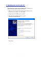
2. Installing the board in the PC (The following description refers to Windows XP. Obviously, on another operating system it might be different.) 1. Make sure that all installation files have been copied to your hard disk to a new folder, say, LCIC-WIM. 2. Connect the LCIC-WIM board to your PC. 3. The ‘Found New Hardware Wizard’ appears. Select the last option like this: Click ‘Next’.
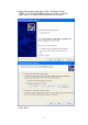
4. Select the second option, click ‘Next’ and browse to the “FTDI - VCP (Virtual COM Port) Driver” folder (under the folder where you copied the installation files in step 1). Click ‘Next’.
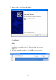
5. After a while, you’ll have this display: Click ‘Finish’. Notes 1. It might occur that the wizard will return to step 3, requiring to repeat the process. This is normal, just repeat steps 3-5. 2.
3. Utilities 3.1 Setup & Running 1. Run the setup(s) of the LCIC-WIM utilities in the folders: * LCIC-WIM-CALIBRATION * LCIC-WIM-SETTINGS 2. Run a utility: * If the utility reports that .Net Framework is not installed, then run "dotnetfxV1.1.4322.exe" in the "Microsoft Net Framework" folder on your CD. * If the utility reports "LCIC driver is not installed", then refer to the previous section (“Installing the board in the PC”).
3.2 The Calibration Utility 3.2.1 General The calibration utility (LCIC-WIM-CALIBRATION) enables to calibrate the LCIC-WIM board adjusting it to your own system. The utility is straightforward and is in the form of a Windows wizard. It includes three main stages carried out in five steps. The three stages are: 1. Show Data (step 1) (Described below under ‘Step 1’.) 2.
The five calibration steps are: Step 1 – Show Data This step introduces both the parameters and the current readings, as received from the board. The step is passive in the sense that it only shows data passed by the board, but it does not make any change in the board. Some additional parameters may be displayed in the bottom of the “Current Board Calibration” box.
Step 2 – Pseudo Calibration / Parameters This step starts the calibration procedure. It enables to change calibration parameters. Whether you changed the parameters or not, you may proceed to the next step by pressing the ‘Next’ button. Library issues: 1. Alternatively, you may click ‘Library’ in order to access the library, as described in the ‘Calibrations Library’ section. (If there are still no calibrations in the library, the ‘Library’ button will be inactive.) 2.
Step 3 – Pseudo Calibration / Zero This step enables to redefine the ‘zero’ level. Click ‘Skip’ if you are satisfied with the previous definition of the ‘zero’ level. Otherwise, when the scale is empty and stable (see note), click ‘Zero’ to sample another ‘zero’ level. Once you clicked ‘Zero’, you may either confirm the new ‘zero’ level by pressing ‘Next’, or redefine it by clicking again the ‘Zero’ button, or leave it out by clicking ‘Skip’.
Step 4 – Pseudo Calibration / Weight This step enables to redefine the ‘weight’ level. Click ‘Skip’ if the previous ‘weight’ level was OK. Even if there was a fixed shift in the weight (which you probably corrected in step 3), you don’t have to redefine the ‘weight’ level – just click ‘Skip’. Otherwise, specify the value of the weight, and when the weight is stable on the scale, click ‘Ready’ to sample another ‘weight’ level.
Step 5 – Save or Quit This is the final step – here you decide whether to confirm the pseudo calibration, or leave it out. Before you decide, you may watch the current readings examining whether they are satisfactory.
3.2.2 The Calibrations Library Each calibration that the user applies may be saved in the ‘Calibrations Library’. Later on, the user may use that library as a short cut in order to restore a previous calibration quickly and reliably. The procedure is very simple: Save Unless the ‘Save to Library’ box is unchecked, each calibration is automatically saved to the library upon its saving to the board in Step 5. Its name is the ‘Calibration Name’ parameter.
3.2.3 Parameters TThhiiss sseeccttiioonn ddeessccrriibbeess tthhee ppaarraam meetteerrss ttoo bbee ffiilllleedd dduurriinngg tthhee ccaalliibbrraattiioonn pprroocceedduurree. Parameter #1: Load Cell mV/V The mV/V output of your load cell: 1, 2 or 3 mV/V. In case the actual output is none of these values: choosing a value higher than the actual will result in loss of resolution; choosing a lower value may result in loss of range, that is, maximum smaller than the real one. Refer also to Appendix B.
3.2.4 Calibration Efficiency (CE) The potential range of A/D points is between 0 and near ±8,400,000. The 'Calibration Efficiency' specifies what portion of this potential range is in use. The closer it is to 100%, the better accuracy / stability you have. However, in practice , 100% is a theoretical number and almost not reachable . The accuracy and stability will still be excellent even if 'Calibration Efficiency' is far lower than 100%.
3.3 The Settings Utility The LCIC-WIM-SETTINGS utility gives control to card’s filters, analog output, fill mode parameters and more. The utility has three items: • The Menu Bar • Current Weight Display • Parameters The ‘Current Weight Display’ is rather obvious – it continuously shows the actual weight. The other two items are detailed below. 3.3.1 The Menu Bar The Menu Bar supplies some functions: • Exit An alternative way to quit the utility. • Tools / Analog Output Described below (section 3.3.1.1).
3.3.1.1 Tools / Analog Output The ‘Settings’ utility gives access to the analog output mechanism: Click ‘Tools’ / ‘Analog Output’. For ‘manual’ mode uncheck the ‘Activate Auto Mode’ box. For ‘auto’ mode check the ‘Activate Auto Mode’ box. Manual Mode On the top of the display, specify a desired voltage in the ‘Manual Mode’ square and click ‘Send’. Auto Mode Specify the following parameters: 1. Voltage Max. 2. Weight Max. 3. Weight Min. 4.
3.3.1.2 Tools / Baud Rate for SCI port Click ‘Tools’ / ‘Baud Rate for SCI port’ to see the current baud rate for the RS232/RS485 serial port. It may be changed to some values between 19,200 and 115,200. (The baud rate for the USB need not be defined – usually it is 921,600.) The change will take effect only after card reset. The current b/r used by the board for the serial communication is shown for a while on the LED display upon card reset, prefixed by ‘Sb’ (=Serial baud rate).
3.3.1.3 Tools / General Setpoints The LCIC-WIM board has four digital outputs. Each of them may be defined – through the Tools / General Setpoints – either as a manual output, or as a general setpoint output: • A manual output is controlled by a user’s command sent from the PC (or another computer). That is, the user sends – either by his own application or by a general RS232 terminal (see section D.3) – commands to turn an output on or off.
3.3.2 Parameters The following sections describe the various parameters. After changing parameter(s), click the ‘Save to Board’ button and wait a while until the new value(s) are accepted by the board. 3.3.2.1 Communication The Communication box refers to card’s communication port – either serial or USB. The current Port and Baud Rate are shown. They are ‘read only’, that is, not changeable. (About changing the Baud Rate for a serial port, refer to section 3.3.1.2.
3.3.2.1.4 Get results immediately Controls card’s response in communication during a special mode, such as the Fill mode: When checked, the card assumes that the PC (or another remote computer) is continuously connected and listening to the communication port. Therefore, the card takes the initiative and sends messages to the PC, reporting the process results immediately when they are available.
3.3.2.2 Auto Zero The ‘Auto Zero’ optional feature supplies an automatic correction to creeps in the zero level during a special mode (such as the fill-mode or the WIM-mode), caused by dust, temperature etc. When this feature is activated and the card is inside the special mode, the board automatically clears the gross weight if some pre-defined condition is satisfied: All readings within some ‘continuous duration’ are inside the ‘zero range’.
3.3.2.3 Start Fill-mode 3.3.2.3.1 Fill-mode starts automatically upon card reset When this option is activated (checked), the card starts automatically the Fill-mode upon reset. Otherwise (the option is unchecked), the cards ‘awakes’ in the upper level, referred to in this document as the ‘general mode’. Notes 1. In order to switch the card from Fill mode to General mode, use the ‘x’ command (small ‘x’). 2. In order to switch the card from General mode to Fill mode, use the ‘F’ command. 3.
3.3.2.4 Filtering Board’s digital filtering is used to "smooth" the read samplings by averaging a pre-set number of the internal readings. It's especially essential on a noisy environment, as this mechanism reduces system's susceptibility to short interferences. The 'noise' may be either mechanical (e.g., load cell vibrations), or electrical. The digital filter averages the raw internal readings of the A/D, whose rate is 52,734 A/D readings per second.
4. Programming your Application The control of the board is by commands and parameters, described below. You may either use them directly (see also section D.3), or call an ActiveX (see section 4.3) that does the work. 4.1 Commands _ signifies a carriage return. Note about High Speed Commands: Single character commands (where no is required) are used for quick direct access/control of the card. Command Action a. Parameters: Read & write: Read parameter #nn.
c. Get a single reading of: weight, A/D or temperature: . ? > < T Get weight (after Filter2, not rounded to resolution). Get weight (after Filter2, rounded to resolution). Get A/D reading after Filter1. Get A/D reading after Filter2. Get temperature d. Analog output: Read & write voltage: @ vx (lower case v) Gets the analog output voltage (in Volts). Sets the analog output voltage to x Volts. The analog output voltage is measured at pin 12 of CONN6 with respect to pin 13 which is ground. e.
h. RS485: Address selection, setting & reading (for more details and examples refer to section D.5; except ‘Nx’, these commands are available also in the fill mode): :x :999 n Nx Activate the board addressed x. x is between 1 and 64. Notes 1. Wait 10 ms after sending the colon (‘:’) before sending the rest of the command (‘x’). 2. Wait 30 ms after sending the ‘:x’ command before analyzing the response(s). “Hello” command: prompt all existing boards to respond. Notes 1.
i. Misc.: z (lower case z) Z (Upper case Z) (versions 1.12, 3.09, 6.01, 7.00 and up) S (upper case S) F (upper case F) V (upper case V) Manually zero the gross weight. The effect of this function is temporary — it expires upon card reset. Response (versions 1.12, 3.09, 6.01, 7.00 and up): ‘z’. Cancel the manual zero operation (the lower case ‘z’). That is, return to the original calibration zero. Response: ‘Z’. System reset (software reset to perform a restart as if turned off/on).
Summary of Weight & A/D Reading Commands A/D Single Reading Fast Mode .
4.2 Parameters Parameter number 1 2 3 4 5 Parameter Description Load Cell mV/V (1, 2 or 3. 0 = unknown). Units: 0=g, 1=kg, 2=ton, 3=oz, 4=lb. Full Load Cell(s) Capacity Maximum Applied Capacity Resolution Index (0-17) Resolution Index is actually the index to an array of 18 defined values(0-17) like that: 0.0001, 0.0002, 0.0005, 0.001, 0.002, 0.005, 0.01, 0.02, 0.05, 0.1, 0.2, 0.5, 1, 2, 5, 10, 20, 50. 8 11 20 E.g., if Resolution Index=8, then system resolution = 0.05.
23 24 25 101 102 103 104 111 112 113 114 115 Filter1 value: 2-256. Becomes effective only after a system reset (either power off/on or using the ‘S’ command). Filter2 value: 2-256. Becomes effective only after a system reset (either power off/on or using the ‘S’ command). Decimator: 1-1000. Becomes effective only after a system reset (either power off/on or using the ‘S’ command). General Setpoint1. Becomes effective only after a system reset (either power off/on or using the ‘S’ command).
1024-1034 1053 1054 1055 1059 1066-1069 Calibration Name (32 characters max.) (Organised 3 characters per location; in case the length is less than 32, the last character is followed by a binary zero byte.) Analog Output Max Voltage Analog Output Min Weight Analog Output Max Weight Analog Output Mode (0 = Manual, 1 = Auto) Card Serial Number (12 characters max.) (Organised 3 characters per location, in case the length is less than 12, the last character is followed by a binary zero byte.
4.3 LCIC-WIM ActiveX Unless otherwise specified, a function returns a Boolean: True for success, or False for failure. 4.3.1 Start/Stop Communication Is_LCIC_WIM_Port(CommPortNumber) Returns: 0 if the port does not respond. 1 if the port responds but not as an LCIC-WIM. 2 if the port responds as an LCIC-WIM. CommPortNumber (Integer): Number of communication port. OpenLCIC_WIM(CommPortNumber, Baud_Rate) Opens the specified port. CommPortNumber (Integer): Number of communication port.
4.3.2 Variables The system has variables with which the user may adjust the system to his needs and communicate with the I/O. Actually these variables consist of parameters, inputs and outputs. A variable may be read and sometimes also may be written. The table below lists the variables, describes them and specifies which of them may be also written. The methods to read and write a variable are: Read: Get_Variable(r) Returns a string with the value of the variable.
Variables Table Category Variable Name Calibration_Name Calibration_Date Calibration_Time Unit Calibration Info Resolution Full_Capacity Maximum_Load Load_Cell_Output Filter1 Filtering Filter2 Decimator Description Name of calibration Calibration date (MMDDYY). Calibration time (HHMM, e.g., 1545). Weighing unit: ton, kg, g, lb or oz. Weighing resolution: 0.0001, 0.0002, 0.0005, 0.001, 0.002, 0.005, 0.01, 0.02, 0.05, 0.1, 0.2, 0.5, 1, 2, 5, 10, 20 or 50. Full capacity of the load cell.
Variables Table (cont’d) Category Variable Name Weight_Native Analog Inputs Weight_Rounded A2D_F1 A2D_F2 Temperature Digital Outputs Output_1_Mode Output_2_Mode Output_3_Mode Output_4_Mode Output_1_Status Output_2_Status Output_3_Status Output_4_Status Output_A_Status General Setpoints Setpoint_1 Setpoint_2 Setpoint_3 Setpoint_4 Description Current weight after Filter2, not rounded. Current weight after Filter2, rounded to resolution. Current A/D after Filter1. Current A/D after Filter2.
Variables Table (cont’d) Category Analog Output (The analog output voltage is measured at pin 12 of CONN6 with respect to pin 13 which is ground.) Variable Name Analog_Output_M ode Analog_Output_ Level Auto_Hi_Voltage Auto_Lo_Weight Auto_Hi_Weight Digital Inputs Description Get Set 0 = Manual, 1 = Auto. V V V * V V V V V V Voltage in the analog output, in volts (0 – 2.5). * The ‘Set’ is relevant only if Analog_Output_Mode is ‘Manual’.
Variables Table (cont’d) Category Variable Name Fast Mode FM_Updates Misc. Version_ID Serial_Number Description Get FM_Updates = Each how many internal updates there will be a Fast Mode transmission (3 – 52,734, integer). The frequency of the internal updates is 52,734 Hz. So, the theoretical reading rate is from 17578 per sec to 1 per sec. (52734/FM_Updates). Practically, the actual rate for V low values of FM_Updates is usually less than the theoretical rate. Notes: 1.
4.3.3 Filters Set_Filtering(Filter1, Filter2, Decimator) Filter1 (Integer): 2 – 256 or 0. Filter2 (Integer): 2 – 256 or 0. Decimator (long): 1 – 1000 or 0. (Refer to the ‘Filtering’ square in the variables table above.) Set_Filtering supplies a faster way to change the filtering parameters when more that one of them has to be changed, as the change operation causes board reset which is time consuming; individual activations of Set_Variable would require this time more than once.
4.3.4 Fast Mode (The Fast Mode is not available with RS485.) During the Fast Mode there is auto high speed transmission of weight readings to the communication. About the transmission rate, refer to the ‘Fast Mode’ square in the variables table above. At the end, a ‘timer stamp’ is appended. Its value is the time elapsed from start of transmission until end of transmission, in ms.
The mechanism to receive the data uses events and methods as described below: The transmission sends blocks of information. Stage 1 Except the last one, each block generates the event DataArrivalInFastMode. When the event occurs, run the method Get_CurrentBlock to read the current block. The block consists of integer weights separated by a Carriage Return. At this stage, just store the blocks into a string array. This stage repeats until the last block arrives.
How to work with the Fast Mode in VB using the ActiveX During the Fast Mode process the board transmits mass data to the PC. Therefore, in order to avoid data loss, all the actions on your PC should be minimized. 1. Define string Array Dim Fast_mode_Data(1 to SizeOfArray) as String Dim fmCounter as long 'Current counter (index( 2. Select Filter: Filter=Filter2 3. To start the Fast Mode: Call LCICwim_commands1.Start_Fast_Mode(Filter( 4.
Interpreting the data in a block: Each block includes integer weight values separated by a c/r. In order to get the real weight values, the integer values should be multiplied by the current Resolution Factor (for details refer to the end of stage 3, above). You may get the current Resolution Factor using the method: LCICwim_commands1.Get_Resolution_Factor 4.3.5 Misc. Apply_Temporary_Zero() Manually zero the gross weight. The effect of this function is temporary — it expires upon card reset.
Appendix A: I/O & the LED Display A.1 General Notes about the I/O * The digital I/O is available on CONN6 (15 pin Dsub). * Digital Outputs The outputs are opto-isolated 300mA 50V solid state relays. When activated (status LED is on), they switch the OUTPUT x (x=1,2,3, or 4) to I/O VOLTAGE OV. Hence the load would normally be connected between OUTPUT x and the I/O VOLTAGE+. * Digital Inputs The digital inputs are designed to work with either npn or contact input devices.
* Connections The following table shows the I/O pinout: Pin Function 1 2 3 4 5 6 7 8 9 10 11 12 13 14 15 Output 1 Output 2 Output 3 Output 4 Input 1 Input 2 Input 3 Input 4 I/O Voltage 0V NC NC Analog Out Signal Analog Out Gnd NC I/O Voltage+ (10 to 30V) 49
A.
A.
A.4 The LED Display Upon board restart, the two following messages are shown on the LED display – each for a while: LCIC x.xx x.xx is board’s DSP version. Sb yyy yyy is current board’s Serial baud-rate (refer to sections 3.3.1.2 & D.2). Then the display shows the current data. Notes 1. The weight on the LED display is always after Filter2 (refer to section 3.3.2.4). 2. In Fill-mode, the LED display shows additional information – refer to section E.5. 3. During the Fast Mode (section 4.3.
Appendix B: Scaling the Load Cell Input The full scale of the input coming from the load cell may be adjusted by the LK4 jumper (which is next to load cell connector): • Across the two leftmost pins (default): Load cell output is 1-2mV/V. • Across the two rightmost pins: Load cell output is 3mV/V.
Appendix C: Load Cell Connections 54
Appendix D: USB, RS232 & RS485 In addition to USB, The LCIC has an option for both full-duplex RS232 and half-duplex RS485 interfaces. These are brought out on CONN3, a 9 way ‘D’ type connector. The pin-out is as follows: CONN3 PIN 1 2 3 4 5 6 7 8 9 FUNCTION RS485RS232 TX (out) RS232 RX (in) NC SIGNAL GROUND RS485+ NC NC NC i.e.
D.2 Baud Rate For the USB, the maximal baud rate is 921,600. The board responds well without a need to pre-define the used b/r. For serial communication, the required b/r should be pre-defined by the user via the Settings utility (section 3.3). The available baud rates are between 19,200 and 115,200. The current b/r used by the board for the serial communication is shown for a while on the LED display upon card reset, prefixed by ‘Sb’ (=Serial baud rate). Refer also to sections 3.3.1.2 & 3.3.2.1.2. D.
D.5 RS485 Up to 64 LCIC-WIM boards may be connected to one PC port. In the PC side, use a converter either from the RS232 port, or from the USB port (that is, RS232 to RS485 converter, or USB to RS485 converter). In the board side, use the serial port (CONN3) – refer to the table in the beginning of this appendix. Using the LCIC-WIM-SETTINGS utility, each board is assigned a unique address between 1 and 64 – refer to section 3.3.2.1.3 (never give the same address to more than one board).
RS485 Commands Except ‘Nx’ (paragraph d), these commands are available also in the fill mode. a. Activate address x (x=1, 2, 3, …, 62, 63, 64): :x Board(s) response: 1. If address x is already active: !x (The board reports that it is already active and has nothing to do.) 2. If address x is not active: 2.1 If another address is currently active: ^x (I’m going to sleep) (The ‘falling’ board reports that it received an activation command to another board, then it makes itself inactive.) 2.
Notes 1. Wait 10 ms after sending the colon (‘:’) before sending the rest of the command (‘x’). 2. Wait 30 ms after sending the ‘:x’ command before analyzing the response(s). 3. There might be four cases with the conditions of 2.1 & 2.2: #1: Both conditions are true: Both responses will be transmitted – first ‘^x’ and then ‘Ax’. (Old address retired and address x became active.) #2: None of the conditions is true: There will be no response.
b. Hello: :999 The ‘hello’ command is like a ‘who is alive?’ question. This is useful in order to detect which addresses exist in the system. Each existing board, whether active or not, responds ‘*x’, where x is its address. Notes 1. Wait 10 ms after sending the colon (‘:’) before sending the rest of the command (‘999’). 2. The ‘*x’ responses will be transmitted in sequence.
c. Read the RS485 address of the active board: n Board’s response: ’#x’, where x is the address of the active board. x=0 means that the board has been configured as a non-RS485 device. Other value (between 1 & 64) specifies the RS485 address of the active board. Notes 1. After sending the ‘n’ command, wait 1 second to give chance to all 64 potential addresses to respond. 2. If no board is active, there will be no response. 3.
RS485 Responses (Most responses are already described in the ‘Commands’ section.) !x ^x Ax *x ?x #x Address x is already active. See Commands/a/1. Becoming inactive on behalf of address x. See Commands/a/2.1. Address x becomes active. See Commands/a/2.2. Address x is alive. See Commands/b. A ‘:x’ command was received but x is illegal. That is, x is neither in the range (1,…,64), nor 999. Address x is active. See Commands/c.
Examples Suppose there are 3 boards in the system, addressed 1, 2 & 3. (The blue text is the PC side, the red text is the response from the board(s), and the black text is our comments) Example #1: Everything goes fine :999 *1 *2 *3 n (no response as no board is active) :1 A1 Board #1 becomes active n #1 :2 ^2 Responded by board #1. Means: I (board #1) am becoming inactive in favor of board #2, even though it’s unknown for me whether board #2 exists or not. A2 Responded by board #2.
So far everything was smooth; however, the quality of the communication depends – besides the board and the PC – also on the environment. Hence, there might be irregular situations that the user should know to handle – this is what the following two examples (#2 and #3) explain.
Example #3: No response from the old board n #1 :2 A2 Board #2 becomes active But the ‘^2’ response, telling that board #1 became inactive, did not arrive! Where is the disorder? Maybe board #1 did receive the command and is indeed inactive, just the ‘^2’ response was lost, and everything is OK (case #1); but maybe board #1 did not receive the command and both boards are active (case #2). This is a dangerous situation and definitely should be avoided.
Board selection by the supplied utilities The three supplied utilities – LCIC-WIM-CALIBRATION, LCIC-WIMSETTINGS & LCIC-WIM-MONITOR – enable easy selection of the required board: • Upon program start, all detected addresses are reported. Verify that the total number of boards detected (reported at the bottom of the display) corresponds the real number. It might occur that the automatic detection fails to detect a board.
Appendix E: Fill Mode E.1 Introduction The LCIC-WIM supplies a Fill Mode in which it may control a filling operation, using the hardware inputs (section E.2) and hardware outputs (section E.3). The character of the filling operation is determined by parameters (section E.4) set via the Settings utility (section 3.3). The filling results are shown on the LED display (section E.5). The Fill Mode supports also commands (section E.6) sent through the communication line (USB, RS232 or RS485).
E.2 Hardware Inputs Input #1 OFF = Manual Input #2 Input #3 ON = Turn output #1 on ON = Turn output #2 on ON = When Terminate in error an Error status: Status ON = Auto ON = Start When not in error status and not during filling: Long ON = Special Mode (*) Input #4 N/A ON = Emergency Stop * The Special Mode In this mode: * ‘SP’ flashes on the left side of the LED display. * The three setpoints are shown, in turn, on the LED display.
E.3 Hardware Outputs Output #1 Output #2 Output #3 Output #4 Option #1 Fast Valve Slow Valve Error Option #2 Fast Valve = Output #1 + Output #2 Slow Valve = Output #2 only (About Options #1 and Option #2 refer to ‘Fast Speed Config’ in section E.4.3) 69 Filling Complete (Only with board firmware 1.11 or higher.
E.4 Filling Parameters Notes 1. There is a set of three setpoints. Once they are specified (using the Settings utility), the user may switch to another setpoint without needing a PC. This gives more flexibility when several setpoints are needed. For details about the switching procedure refer to section E.2. 2. These setpoints are absolutely different from the four general setpoints (section 3.3.1.3). The general setpoints are inactive in the Fill mode.
Auto Correction & Averaging x last fillings When ‘Auto Correction’ is checked, the board tries to correct the filling amount, based on the results of the last x fillings. E.4.1.2 Auto Tare Activate • When not checked, the Setpoint defines the requested final gross weight. That is, if the setpoint is 100 kg and the starting gross weight is 90 kg, the filling amount will be 10 kg. The next two parameters (Hi/Lo Limits) are irrelevant. • When checked, the Setpoint defines the requested filling amount.
E.4.1.3 Valid Results Limits The resulting filling weight should normally be inside a user pre-defined ‘valid range’. In case the weight exceeds that range, an error situation will occur. Specify ‘Valid Limits (±)’= 0 if you don’t need this check. Start from filling # … Specifies the first filling to be checked, letting you disregard some filling until the board learns the system thus gives good results.
E.4.1.4 Stabilization Criterion (Tare & Stop) At the beginning and at the end of a filling cycle the board waits for the scale to stabilize in order to read its weight. Hence, some stability criterion is required. The board requires that all readings within ‘Delta Time’ will be inside a range whose width is ‘Delta Weight’, both at the beginning (Tare) and at the end (Stop) of the filling cycle. The waiting for that stabilization is limited by ‘Timeout’, causing an error situation in case of failure.
E.4.2 Filling By = Time E.4.2.1 Filling by Time Parameters Setpoint #x The required total filling time when the user selects setpoint #x (x = 1, 2 or 3). Slow Amount The required slow filling time, in % of the current Setpoint (a tip shows the value of Slow Amount in ms). Specify ‘0’ when only one speed is required. E.4.2.2 Stabilization Criterion (Stop) At the end of a filling cycle the board waits for the scale to stabilize before proceeding to the next cycle.
E.4.4 The Filling Configurations Library There is a ‘Filling Configurations Library’ in which you may save sets of filling configuration parameters. This is useful in case you have more than one type of filling, letting you switch easily and reliably from one configuration to another. (Note: This library has nothing to do with the calibration library mentioned in section 3.2.2.) Refer to the ‘Library’ box.
E.
E.6 Commands Enter & Exit Fill Mode F x Enter Fill Mode (from General Mode) Exit Fill Mode (to General Mode) (small ‘x’) Inside the Fill Mode g Start filling (‘g’ stands for ‘go’) (like input #2 does). t Terminate an error status (like input #3 does). e Emergency stop (like input #4 does). r Get filling(s) report Response Example: # 1 A= 40.99 Tr= 6.65 Cv= 0.00 Ft= 7527 ms St= 2554 ms Cc= 0 Legend: Filling #1, Actual (=final) weight=40.99, Tare=6.65, Correction Value=0.
s Get current status (small ‘s’) Response Example: Current_Status: W= 17.14 Tr= 6.65 Cv= 0.00 M=F A=I S= 0 Legend: Current (gross) weight=17.14, Last Tare=6.65, Next Correction Value=0.00, Mode=Fill mode, Activity=Idle (or: Tare, Fast, Slow) System staus=0 (0 is normal, otherwise it’s an error code). p Get parameters list (small ‘p’). i Turn off the “Get results immediately” feature. I Turn on the “Get results immediately” feature. V Get current mode (upper case V). Board’s response: ‘Fill-mode’.
E.7 Error Codes 101 102 103 104 105 106 107 108 109 111 112 113 115 116 117 118 119 120 121 122 123 Actual Filling Weight < Low Limit of 'Valid Result Limits'. Actual Filling Weight > High Limit of 'Valid Result Limits'. SetPoint < Low Limit of 'Valid Result Limits'. SetPoint > High Limit of 'Valid Result Limits'.
Appendix F: Specifications F.1 Load Cell Input • 5 Volt excitation for upto 10 load cells (350 Ohm) • Compatible with 1, 2 & 3 mV/V load cells • Low noise wide bandwidth amplifier & 24 bit ADC F.2 A/D • Very high speed A/D: upto 52,000 samples per second • 24 Bit A/D with ± 8 million counts for tension and compression applications F.3 Digital Inputs • 4 opto-isolated inputs with 10-30 VDC range, each with status LED • Input #2 configurable as high speed counter F.
Appendix G: Trouble-shooting G.1 Card does not respond after PC power-on Q. Everything was OK, but after PC restart the card suddenly stopped responding. A. As specified in section D.4, after PC power on or off the serial communication (RS232/RS485) is likely to drop. A card reset is needed in this case.
Appendix H: Zero & Tare There are two functions which are similar, yet actually different: Zero & Tare: • The Zero function supplies both manual and automatic ways to clear the gross weight. • The Auto-Tare function supplies a way to define the meaning of the setpoint parameter. H.1 The Zero function This function supplies both manual and automatic ways to clear the gross weight: Manual Zero The manual zero is available only in the general mode, not in the fill-mode.
H.2 The Auto-Tare function This function supplies a way to define the meaning of the setpoint parameter: * When the ‘AutoTare’ option is not activated, the setpoint defines the requested final gross weight. That is, if the setpoint is 100 kg and the starting gross weight is 90 kg, the filling amount will be 10 kg. * When the ‘AutoTare’ option is activated, the setpoint defines the requested filling amount.
WARRANTY/DISCLAIMER OMEGA ENGINEERING, INC. warrants this unit to be free of defects in materials and workmanship for a period of 13 months from date of purchase. OMEGA’s WARRANTY adds an additional one (1) month grace period to the normal one (1) year product warranty to cover handling and shipping time. This ensures that OMEGA’s customers receive maximum coverage on each product. If the unit malfunctions, it must be returned to the factory for evaluation.
Where Do I Find Everything I Need for Process Measurement and Control? OMEGA…Of Course! Shop online at omega.