Operator ’s Manual OjyjEGA ENGINEERING, INC. AnO.VfEG.
WARRANTY OMEGA warrants this unit to be free of defects in materials and workmanship and to give satisfactory service for a period of 13 months from date of purchase. OMEGA Warranty adds an additional one (1) month grace period to the normal one (1) year product warranty to cover handling and shipping time. This ensures that our customers receive maximum coverage on each product. If the unit should malfunction, it must be returned to the factory for evaluation.
TABLE OF CONTENTS Page No. PART I - INTRODUCTION Specification s General Descriptio 1 2 n PART II - INSTALLATION 1. 2. 3. Unpacking Mounting Wiring PART III - OPERATION INSTRUCTION TECHNICAL INFORMATION 1. 2. 2 2 3 & Controls Operation 4 4/s PART IV - CALIBRATION 1. 2. 3. PART 1. 2. 3. 4.
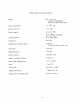
MODEL PHTX-11 SPECIFICATIONS Spans: Any 1 thru 14, jumper programmable zero and span adjustable Input Impedance: 1 x 10¹³ ohm Output Current: 4 to Power Supply: 12 to 80 VDC 2onlA ii Ez iim+DC>O~~~ONAL Load Resistor: 0 to 3400 ohms Linearity: *.Ol pH Temperature Coefficient: f. 02%/OC (Display and current out) Accuracy: ht.01 pH Repeatability: k.01 pH Output meter: 3% digit Supply Voltage Effect: .Ol%/Volt Operating Temperature: -10 to +60°C R.H.
PART I - INTRODUCTION General description The OMEGAmModel PHTX-11 is a 2-wire pH/ORP transmitter featuring input-output isolation, wide power supply range, high input impedance, LCD digital display, modular construction, programmable span selection, manual/automatic temperature compensation and a NEMA 4X housing as a standard enclosure. The Model PHTX-11 accepts as its input any pH probe via a BNC co-axial connector. It transforms the probe signal to a 4 to 20mA D.C.
2.4 Panel Mounting - refer to Table II for hole sizes and locations. mounting requires the PVC mounting feet and four PVC mounting blocks. The blocks are drilled and tapped for #lo-24 screws. 3. This Wiring 3. 1 After the enclosure is properly mounted the wires for input, output, ground and remote temperature sensing should be routed through the enclosure hubs. These connections should be trimmed to the proper length and connected to the circuit board assembly.
PART III 1. 2. - OPERATING INSTRUCTIONS & TECHNICAL INFORMATION Controls 1.1 Display switch is 1abeled"Press for mA" on the cover. The display will indicate 0.00 pH to 14.00 pH when the switch is in the relaxed position. When the switch is pressed and held, the display will indicate the output current to mA, normally 4.0 mA to 20.0 mA. 1.2 "pH CAL" potentiometer is an offset adjustment for the pH probe on the input circuit board.
2.3 Test the display by pressing the display switch. indicate PART IV The display should mA and the decimal point should shift one place to the right. - CALIBRATION The recommended calibration interval for the transmitter is six months under normal operating conditions, and assuming the sensor is in good condition. This system may need adjustment to compensate for reduced efficiency of the sensor before the calibration interval. Equipment Required 2.1 pH Simulator or a millivolt source. 2.
RANGE #3 is with jumpers al, #2, and #3 in place. pH units. for a span of 1 or 2 The output is adjustable 3.6 SPAN h ZERO adjustments interact and require going back and forth between Connect a millivolt source, them. or preferably a PII simulator at the input, a resistor at the temperature compensation terminals. Adjust (Refer to Table I for the correct resistor and millivolt values). for 20 mA at the desired pH levels.
----!-! _ - < l _ __ iI_ i I --- ‘ -7 -
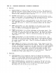
TABLE Temp. O'C oH mv. 0 +379.3 2 3 1 5 6 +325 .1 1-270.1 +216 .8 +162 .6 +108 .4 + 54.19 8 9 10 11 12 13 14 - 54.1 9 -108. 4 -162. 6 -216. 8 -270. 1 -325. 1 -379. 3 I I 50°C mv. 7o c ” +414-o +434 .9 +354 .9 +372 .8 +295 .a +310 .7 ‘236. 6 +248 .5 +177 .5 +186 .4 +i18.3 +124 .2 + 59.15 + 62.13 +448-a +476 .6 +408 .5 +340 .5 i272. 4 +204 .3 +136 .2 + 68.0 9 +504 .4 +432 .3 ~360 .3 1-288.2 t-216.2 +144 .1 + 72.0 5 +518.2 +384 .7 +320 .6 +256 .5 +192 .-l +12a . 2 + 64 .12 - 59.15 - 64.
- b v- 1
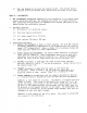
TABLE II PAN EL CUT-OUT ’ 7 .t DIA.
FAX 1M31359-Tmo QWKE%k,. .