MADE IN User’s Guide Shop online at omega.com e-mail: info@omega.com For latest product manuals: omegamanual.
OMEGAnet ® Online Service omega.com Internet e-mail info@omega.com Servicing North America: U.S.A.: ISO 9001 Certified Canada: One Omega Drive, P.O. Box 4047 Stamford, CT 06907-0047 TEL: (203) 359-1660 e-mail: info@omega.com 976 Bergar Laval (Quebec) H7L 5A1, Canada TEL: (514) 856-6928 e-mail: info@omega.ca FAX: (203) 359-7700 FAX: (514) 856-6886 For immediate technical or application assistance: U.S.A.
WARRANTY/DISCLAIMER OMEGA ENGINEERING, INC. warrants this unit to be free of defects in materials and workmanship for a period of 25 months from date of purchase. OMEGA’s WARRANTY adds an additional one (1) month grace period to the normal two (2) year product warranty to cover handling and shipping time. This ensures that OMEGA’s customers receive maximum coverage on each product. If the unit malfunctions, it must be returned to the factory for evaluation.
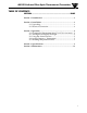
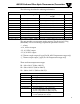
OS1592 Infrared Fiber Optic Thermometer/Transmitter Table of Contents TABLE OF CONTENTS SECTION ..................................................................PAGE Section 1 Introduction ........................................................................ 1 Section 2 Installation ........................................................................... 1 2.1 Unpacking .............................................................................. 1 2.2 Electrical Connection........................
Table of Figures OS1592 Infrared Fiber Optic Thermometer/Transmitter TABLE OF FIGURES FIGURE ..................................................................PAGE 1 OS1592 Main Unit ............................................................................ 3 2 Power Supply and Analog Output Connections ........................... 3 3 Visual Functional Flow Chart .......................................................... 4 4 NEMA-4 Aluminum Enclosure .....................................................
OS1592 Infrared Fiber Optic Thermometer/Transmitter 1 INTRODUCTION The new OS1592 series Infrared Fiber Optic Thermometer/Transmitter provides non-contact temperature measurement for industrial applications. The unit measures temperature starting at 260°C (500°F) and up to 2482°C (4500°F). It provides dual analog outputs (4-20 mA, 0-5 VDC, 0-10 VDC, 1 mV/Deg, J & K type T/Cs) electrically isolated from the main input DC power supply. The 1 mV/Deg analog output is standard on all units.
2 OS1592 Infrared Fiber Optic Thermometer/Transmitter The following describes the ordering information: To Order ( Specify Model Number ) Model No. Temperature Range Optical Assy (Spot Size) Length Cable OS1592-L1-R1-1-* 260/538°C (500 to 1000°F) Lens Probe 6.3 mm (0.25") @ 20.3 cm (8") 1.52 m (5') OS1592-L2-R1-* 260/538°C (500 to 1000°F) Ceramic Tip, 15.2 cm (6") Probe 1.52 m (5') OS1592-L3-R1-* 260/538°C (500 to 1000°F) Polymer Bolt, 10.2 cm (4") Probe 1.
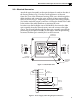
OS1592 Infrared Fiber Optic Thermometer/Transmitter 2 2.2 – Electrical Connection Attach the optical assembly to the optical adapter located on the side of the housing. Refer to Fig. 1 for the overall appearance of the unit. Open the cover of the aluminum housing. Slide your cable through the metal feed thru and connect the wires to the 9 position terminal block (J101) as shown in Fig. 2. Depending on the type of the analog outputs, you need to make the proper connection.
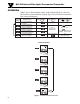
3 OS1592 Infrared Fiber Optic Thermometer/Transmitter OPERATION Table 1 shows all the display modes of the model OS1592, as well as all the functions of the membrane keypad. Fig 3 shows the Visual Functional flow chart of the display.
OS1592 Infrared Fiber Optic Thermometer/Transmitter 3 NOTE: The Emissivity setting as well as the temperature Engineering unit (°F or °C) are stored in the non-volatile memory. Removing the main power will not erase or change these settings. 3.1 - Changing the Temperature from °F to °C (or vice versa) Press the MODE key to go to either the MAX , MIN, or DIF display mode. Press the °F–°C key to change the temperature display from °F to °C or vice versa.
3 OS1592 Infrared Fiber Optic Thermometer/Transmitter 0-5VDC: Measured Temp = [ (Voltage Output ) x (T2 - T1)] + T1 5 0-10VDC: Measured Temp = [ (Voltage Output) x (T2 - T1)] + T1 10 Where, T1 is the minimum temperature range T2 is the maximum temperature range 3.5 - Resetting Temperature Values The calculated temperature values (Min, Max, and Diff) can be reset at any time by pressing the SET key in either the MAX, MIN, or DIF display modes.
OS1592 Infrared Fiber Optic Thermometer/Transmitter 3 111 (4.38) 25.4 (1.00) DIA. FIBER 19 (.75) DIA. Dimensions mm (in.) 159 (6.25) Figure 5 - Optical Lens Assembly (L1) .25" @ 8" FOV FIBER 19 (.75) DIA. 111 (4.38) Dimensions mm (in.) 25.4 (1.00) DIA. 149 (5.87) Figure 6 - Optical Lens Assembly (L1) .19" @ 20" FOV FIBER 19 (.75) DIA. 25.4 (1.00) DIA. 183 (7.22) Dimensions mm (in.) 264 (10.38) Figure 7 - Optical Lens Assembly (L1) .076" @ 6" FOV FIBER 6.35 (.250) DIA. 4.8 (.190) DIA.
3 OS1592 Infrared Fiber Optic Thermometer/Transmitter 72 (2.84) 7.8 (0.307) 7.7 (0.305) 11 (0.414) 10 (0.412) FIBER 45° 12.7 (0.50) 15.7 (0.62) ACROSS FLATS 12.7 ±1.5 (.50 ±0.06) 53 ±1.5 (2.10 ±0.06) 1/2-20 UNF-2A 25.4 ±1.5 (1.00 ±.06) FULL THREAD 102 ±1.5 4.00 ±0.06 5.3 (0.209) 5.6 (0.219) 11 (0.438) Dimensions mm (in.) AIR PURGE FITTING 6.35 (0.25) Figure 9 - Polymer Bolt Assembly (L3) with 90° Angle Air Purge Fitting o.156 TOP 6.35 (0.25) LIP 6-32 UNC 12.7 (1/2) DEEP FROM 3.3 (0.
OS1592 Infrared Fiber Optic Thermometer/Transmitter 4 SPECIFICATIONS Temperature Range R1 260 to 538°C (500 to 1000°F) R2 538 to 1093°C (1000 to 2000°F) R3 1093 to 2482°C (2000 to 4500°F) Accuracy at 22°C (72 °F) ambient temperature and at Emissivity of 0.95 or greater 1% of Rdg. Repeatability 0.5% of Rdg Resolution 1°C or 1°F Response Time 25 msec (0 to 63% of Final value) Spectral Response 0.8 to 1.8 microns Emissivity 0.05 to 1.00 in 0.
4 OS1592 Infrared Fiber Optic Thermometer/Transmitter Display Backlit LCD dual display Keypad switch 4 position, tactile feed back membrane Electrical Isolation Between Input supply and Analog outputs, 1000 VAC Calculated Temperature values Maximum (MAX), Minimum (MIN) and Differential (DIF), Reset via keypad High Alarm LED & Display Icon indication Set & enabled via Keypad Alarm set point 0 to 100%, set via keypad Alarm Deadband 10°C or 18°F Relay Contact rating 5A @ 28 VDC Analog Outputs
OS1592 Infrared Fiber Optic Thermometer/Transmitter 5 MAINTENANCE Routine maintenance is not required except for periodic re-calibration, occasional inspection of the input and output ends of the fiber assembly for cleanliness, and a check for broken fibers if damage is suspected. The optical fibers will provide satisfactory service indefinitely if handled with normal care.
OS1592 Infrared Fiber Optic Thermometer/Transmitter Addendum Safety Warnings and IEC Symbols This device is marked with international safety and hazardous symbols in accordance with IEC1010. It is important to read and follow all the precautions and instructions in this manual before operating or commissioning this device as it contains important information relating to safety and EMC. Failure to follow all the safety precautions may result in injury and or damage to your equipment.
Where Do I Find Everything I Need for Process Measurement and Control? OMEGA…Of Course! Shop online at omega.