User’s Guide Shop online at www.omega.com e-mail: info@omega.
OMEGAnet ® Online Service www.omega.com Internet e-mail info@omega.com Servicing North America: USA: ISO 9001 Certified Canada: One Omega Drive, P.O. Box 4047 Stamford CT 06907-0047 TEL: (203) 359-1660 e-mail: info@omega.com 976 Bergar Laval (Quebec) H7L 5A1, Canada TEL: (514) 856-6928 e-mail: info@omega.
Contents INTRODUCTION.......................................................................................................... 1 OVERVIEW........................................................................................................................1 W HAT ’S INCLUDED ........................................................................................................1 INSTALLATION...........................................................................................................
APPENDIX A - TROUBLESHOOTING..................................................................23 APPENDIX B - HOW TO GET ASSISTANCE......................................................24 APPENDIX C - SILK-SCREEN.................................................................................25 APPENDIX D - COMPLIANCE NOTICES.............................................................26 FEDERAL COMMUNICATIONS COMMISSION STATEMENT ....................................26 EMC DIRECTIVE STATEMENT ..............
Introduction and Installation Introduction Overview The OMG-PCI-DIO48 provides two 8255 mode 0 compatible ports providing four eight-bit ports and four four-bit ports. Each can be individually configured as inputs or outputs. When configured as outputs each bit of the four bit ports may be set or reset individually. What’s Included The OMG-PCI-DIO48 is shipped with the following items. If any of these items is missing or damaged, contact the supplier.
Introduction and Installation System Installation The OMG-PCI-DIO48 can be installed in any of the PCI expansion slots. 1. Turn off PC power. Disconnect the power cord. 2. Remove the PC case cover. 3. Locate an available PCI slot and remove the blank metal slot cover. 4. Remove the clamping portion of the bracket from the card. 5. Gently insert the OMG-PCI-DIO48 into the slot. Make sure that the adapter is seated properly. 6.
Technical Description Technical Description The OMG-PCI-DIO48 provides 48 channels of digital I/O configurable as inputs or outputs, which can be utilized for PC based control and automation including sensors, switches, satellite antenna control systems, video and audio studio automation, security control systems, and other industrial automation systems. Software The OMG-PCI-DIO48 ships with the SeaI/O suite of Windows 98/NT/ME/2000 drivers.
Technical Description 3rd Party Software Support Third party software support for many HMI/MMI and other process control software is included on the product installation CD. For the most up to date information on third party software support, please visit http://www.omega.com.
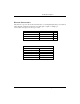
Technical Description Electrical Characteristics The table below provides the electrical characteristics of each Input/Output. Each port is buffered with a 74LS245 octal bi-directional transceiver. Each input is capable of sinking up to 24 mA, while each output can source up to 15 mA. Recommended Operating Conditions Min Input 0V Source Sink Max 5.25 V 15 mA 24 mA Electrical Characteristics High Level Input Voltage Min 2 V Low Level Input Voltage Max 0.
Technical Description Pull Ups Ten pin bussed resistor packs are installed to provide pull-ups to the input ports. These are installed on all ports. The pull-up resistor packs are rated at 10K ohms. Figure 2 below provides the bussed resistor and corresponding port. The resistors insure that no line is floating which is not connected. This provides consistent biasing on all un-terminated lines.
Technical Description 50 Pin Ribbon Pin Out Figure 3-50 Pin Ribbon Cable Pin Out Description Pin # Port A A0 A1 A2 A3 A4 A5 A6 A7 47 45 43 41 39 37 35 33 Port B B0 B1 B2 B3 B4 B5 B6 B7 31 29 27 25 23 21 19 17 Port C OMG-PCI-DIO48 C0 C1 C2 C3 C4 C5 C6 C7 15 13 11 9 7 5 3 1 GND +5V All Even pins 49 Page 7
Technical Description Application Programmers Interface (API) Most modern operating systems do not allow direct hardware access. The SeaIO driver and API have been included to provide control over the hardware in Windows and Linux environments. The purpose of this section of the manual is to help the customer with the mapping of the API to the actual inputs for the 8005 specifically. Complete documentation of the API can be found in its accompanying help file.
Technical Description Port C relative addressing (when port C is split) The input and output nibbles will each be treated as individual four bit ports. Port Configuration: Each eight-bit port can be configured as inputs or outputs. The API provides a set adapter state call to access the control words. For this device, two control word is used. Refer to the following table. Note: : The control panel also allows you to configure the device.
Notes Page OMG-PCI-DIO48 Page 10
Technical Description Tables : API Port/bit reference numbers for Absolute and Relative Addressing R = Read W = Write R/W = Read or Write Port A1 B1 C1 A2 B2 C2 API Port # Absolute Address (function) 0 ( R/W ) 1 ( R/W ) 2 ( R/W ) 8 ( R/W ) 9 ( R/W ) 10 ( R/W ) Figure 5-Absolute byte Address (any configuration) Port A1 B1 C1 A2 B2 C2 Lower C2 Upper API Port # Relative Address (function) 0(R) 1(R) 2(R) 0(W) 1(W) 2(W) 3(R) Port Type Input Input Input Output Output Output Input Figure 6-Relative byte Add
Technical Description Absolute Address Port 1 Absolut Port-Bit e bit Address 0 A1-0 1 A1-1 2 A1-2 3 A1-3 4 A1-4 5 A1-5 6 A1-6 7 A1-7 Port 2 Absolut Port-Bit e bit Address 64 A2-0 65 A2-1 66 A2-2 67 A2-3 68 A2-4 69 A2-5 70 A2-6 71 A2-7 8 9 10 11 12 13 14 15 B1-0 B1-1 B1-2 B1-3 B1-4 B1-5 B1-6 B1-7 72 73 74 75 76 77 78 79 B2-0 B2-1 B2-2 B2-3 B2-4 B2-5 B2-6 B2-7 16 17 18 19 20 21 22 23 C1-0 C1-1 C1-2 C1-3 C1-4 C1-5 C1-6 C1-7 80 81 82 83 84 85 86 87 C2-0 C2-1 C2-2 C2-3 C2-4 C2-5 C2-6 C2-7 Figure 7-Ab
Technical Description The following tables are provided for the user in the event that he/she wishes to record their particular relative addressing setup, provided its constant. Print this page and fill in the tables starting in the top left corner of each and work from top to bottom, left to right. Start with zero on the first input and increment by one on each additional input. Next move to outputs and again start with zero and increment by one on each additional output.
Technical Description C1-6 C1-7 C2-6 C2-7 Figure 9-(Print and fill in for your configuration) Direct Hardware Control In systems where the users program has direct access to the hardware (DOS) the tables below gives the mapping and functions that the 8005 provide. The address of each eight-bit port is calculated as shown in the table on the following page, the cards base address plus an offset. Reading the Inputs: The inputs are active high. If an input is driven high (2V to 5.
Technical Description Interrupts Interrupts can be set up as shown in the tables on the next page.
Technical Description Port C Port C is written and read to as a single eight bit port, but it has the ability to be configured as two four bit ports. If both lower and upper nibbles are configure the same then no special considerations need to be made. But if they are configured differently, one nibble as input, and one as output then the user will have to keep this in mind.
Notes Page OMG-PCI-DIO48 Page 17
Technical Description Control Words n = control word for port1 or 2 I/O Configuration CWnD0 CWnD1 CWnD2 CWnD3 CWnD4 CWnD5 CWnD6 CWnD7 7 1 1 1 1 1 1 1 1 1 1 1 1 1 1 1 1 6 X X X X X X X X X X X X X X X X Port C1 lower nibble (bits 0-3) Port B1 1 = input 0 = output 1 = input 0 = output 0 or 1 (no effect) Port C1 upper nibble (bits 4-7) 1 = input 0 = output Port A1 1 = input 0 = output 0 or 1 (no effect) 0 or 1 (no effect) Always a 1 Control Word (X = 0) 5 4 3 2 X 0 0 X X 0 0 X X 0 0 X X 0 0 X X 0 1 X X 0
Technical Description Bit Set or Reset Port C n = port number CWnD0 CWnD4 CWnD5 CWnD6 CWnD7 1 = set to +5V 0 = Reset to GND 0 or 1 (no effect) 0 or 1 (no effect) 0 or 1 (no effect) Always a zero when using Bit set/reset CWnD3 0 0 0 0 1 1 1 1 7 6 0 0 0 0 0 0 0 0 X X X X X X X X 0 0 0 0 0 0 0 X X X X X X X OMG-PCI-DIO48 Bit Select CWnD2 CWnD1 0 0 0 1 1 0 1 1 0 0 0 1 1 0 1 1 Control Word (X = 0) 5 4 3 2 1 Reset X X 0 0 0 X X 0 0 1 X X 0 1 0 X X 0 1 1 X X 1 0 0 X X 1 0 1 X X 1 1 0 X X 1 1 1 Set X X
Technical Description 0 OMG-PCI-DIO48 X X X 1 1 1 1 0F Page 20 7
Technical Description Interrupt control When enabled interrupts are generated on A10 and A20 (Pin 47 on each 50 pin header), for this reason to use interrupts on a Port its A byte must be set as an input.
Specifications Specifications Environmental Specifications Specification Temperature Range Humidity Range Operating 0º to 50º C (32º to 122º F) 10 to 90% R.H. Non-Condensing Storage -20º to 70º C (-4º to 158º F) 10 to 90% R.H. Non-Condensing Power Consumption Supply line Rating +5 VDC 794 mA Mean Time Between Failures (MTBF) Greater than 150,000 hours. (Calculated) Physical Dimensions Board Length Board Height including Goldfingers Board Height excluding Goldfingers OMG-PCI-DIO48 6.100 inches 4.
Appendix A - Troubleshooting Appendix A - Troubleshooting Following these simple steps can eliminate most common problems. Install software first. After installing the software then proceed to adding the hardware. This places the required installation files in the correct locations. 1. Read this manual thoroughly before attempting to install the adapter in your system. 2. Use Device Manager under Windows to verify proper installation. 3.
Appendix B - How To Get Assistance Appendix B - How To Get Assistance Please refer to Troubleshooting Guide prior to calling Technical Support. 1. Begin by reading through the Trouble Shooting Guide in Appendix A. If assistance is still needed please see below. 2. When calling for technical assistance, please have your user manual and current adapter settings. If possible, please have the adapter installed in a computer ready to run diagnostics. 3.
Appendix C - Silk-Screen Appendix C - Silk-Screen 4.2" 6.
Appendix D - Compliance Notices Appendix D - Compliance Notices Federal Communications Commission Statement FCC - This equipment has been tested and found to comply with the limits for Class A digital device, pursuant to Part 15 of the FCC Rules. These limits are designed to provide reasonable protection against harmful interference when the equipment is operated in a commercial environment.
WARRANTY/DISCLAIMER OMEGA ENGINEERING, INC. warrants this unit to be free of defects in materials and workmanship for a period of 13 months from date of purchase. OMEGA’s WARRANTY adds an additional one (1) month grace period to the normal one (1) year product warranty to cover handling and shipping time. This ensures that OMEGA’s customers receive maximum coverage on each product. If the unit malfunctions, it must be returned to the factory for evaluation.
Where Do I Find Everything I Need for Process Measurement and Control? OMEGA…Of Course! Shop online at www.omega.