User’s Guide Shop online at omega.com e-mail: info@omega.com For latest product manuals: omegamanual.
OMEGAnet ® Online Service omega.com Internet e-mail info@omega.com Servicing North America: U.S.A.: ISO 9001 Certified One Omega Drive, P.O. Box 4047 Stamford, CT 06907-0047 TEL: (203) 359-1660 e-mail: info@omega.com Canada: 976 Bergar Laval (Quebec) H7L 5A1, Canada TEL: (514) 856-6928 e-mail: info@omega.ca FAX: (203) 359-7700 FAX: (514) 856-6886 For immediate technical or application assistance: U.S.A.
TABLE OF CONTENTS GENERAL INFORMATION 1 SPECIFICATIONS 2 INSTALLATION 4 DESCRIPTION OF FUNCTIONS 8 START-UP AND OPERATION 13 OPERATING HINTS 17 UTILITY MENU 18 DIAGNOSTICS 20 TROUBLESHOOTING AND SERVICE 21
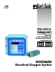
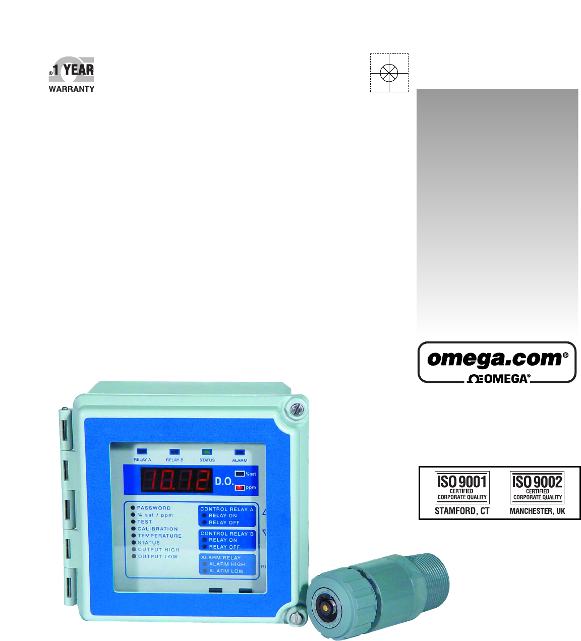
MODEL DOCN600 DISSOLVED OXYGEN ANALYZERS AND MODEL DOE-601 DISSOLVED OXYGEN SENSOR INSTRUCTION MANUAL 1.0 GENERAL INFORMATION The DOCN600 Dissolved oxygen analyzer is a versatile industrial microprocessor based instrument. Outputs are programmed through the menu with push buttons on the face of the instrument. Calibration is also accomplished through the front panel menu. The instrument must be used in conjunction with the DOE-601 dissolved oxygen sensor.
2.0 SPECIFICATIONS MEASURING RANGES: D.O.: 0-20.
MODEL DOCN600 ADDITIONAL FEATURES CONTROL RELAYS: Two relays can be independently set for operation in response to rising or falling value and for fail-safe operation. Deadband (hysteresis) independently adjustable. Rating: 5A 115/230 Vac, 5A 30 Vdc. SPDT ALARM RELAY: High-Low with fixed deadband of 2% of full scale. Normal or fail-safe operation. Rating: 5A 115/230 Vac, 5A 30 Vdc.
3.0 INSTALLATION 3.1 Location 3.1.1 3.1.2 Locate the instrument within the reach of the cable provided for the DOE-601 sensor. Select an installation site which is: • free of mechanical vibrations • reasonably clean and dry • protected from falling corrosive fluids within the ambient temperature and humidity specifications • remote from high voltage relay and power switches 3.2 Type of Mounting 3.2.1 If the instrument is to be pipe or panel mounted a special hardware kit will be required.
3.5 Sensor Installation, Flotation Mounting 3.5.
d) The sensor may be attached to float assembly in one of two ways: 1. With sensor EXTENDED FROM BOTTOM of flotation ball: Insert 12-inch long extender pipe into the flotation ball and fasten it to the end of adapter pipe. This will extend the sensor’s membrane 12 inches below the flotation ball. NOTE: Extender pipe supplied only when ordered. 2. With the sensor membrane FLUSH WITH BOTTOM of flotation ball: Disregard using extender pipe and proceed with Step e).
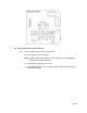
h) Install pivot mounting bracket and mount junction box on the bracket. Insert pipe/sensor assembly through the bracket to the desired position. Tighten pipe locking screw. 3.6 Sensor Installation, Submersion Mounting 3.6.1 a) Refer to diagram below and proceed as follows: b) Route sensor cable through pipe and fasten sensor to pipe. The use of thread sealant (Teflon tape) on all mounting hardware and sensor threads is recommended to avoid leaks.
4.0 DESCRIPTION OF FUNCTIONS 4.1 Overview 4.1.1 The DOCN600 is a microprocessor based dissolved oxygen analyzers are designed for industrial applications. They operate in conjunction with the DOE-601 sensor. The software in the unit makes the instrument very easy to operate and maintain. 4.1.2 The outputs include voltage-free relay contacts and industry standard analog transmission signals. A relay to indicate a perforated membrane is provided.
Some of these are: • • • • • • • • Recall and easy adjustment of relay and output parameters Push button calibration A HOLD function for outputs Continuous sensor check during measurement Continuous self check and watch-dog timer to ensure correct operation Password protection of stored values Temperature Output Simulated input for testing 4.2 Calibration 4.2.1 The DOCN600 is calibrated at the factory, with the sensor purchased with the instrument.
4.6 Analog Outputs 4.6.1 The analog output signals consist of a non-isolated 0-1 mA, 0-5 Vdc, and isolated 420 mA signals. 4.6.2 From the factory all of the analog outputs have a linear range corresponding to the full range of the instrument. The 4-20 mA output can be programmed to another linear range by entering two values: • Output High: This is the D.O. value at which you wish to have 100% output. • Output Low: This is the D.O. value at which you wish to have 0% output. 4.6.
4.7.4 When in the menu mode, the display initially shows the current value of the parameters, such as the Setpoint of the control relay, while putting all of the outputs on hold. The two arrow buttons are used to adjust the display value up or down. To accept the new value press ENTER twice. While the value on the display is being changed, the relay outputs and the analog outputs remain on hold.
Dip Switch Bank S2 1 2 3 4 5 6 7 8 Fail-safe for Relay B Direction of Control for Relay B Reserved Reserved Reserved Reserved Reserved Reserved NO Rising YES Falling 4.9 Output Hold 4.9.1 Output hold, is a function which freezes all output signals at the last value to prevent the occurrence of wild distortions during programming and maintenance. 4.9.
5.0 START-UP AND OPERATION 5.1 Password 5.1.1 To enter the menu press CALL then PASSWORD will be indicated. With each press of CALL you will step through the menu. When the last item is reached the menu wraps around to “%sat/ppm”. If you have enabled PASSWORD by placing DIP Switch 2 Bank S1, in the off position you must enter the password “6” when PASSWORD is indicated if you wish to change any stored value.
i) If you wish to change the measuring unit to ppm, press CALL a number of times to return to “%sat/ppm” and change ppm with the down button. j) Press RUN to return to on line measurement. NOTE: If a major change is necessary to make the display read 100% the display will flash when you press ENTER. This is to warn that you may have made a mistake such as using “stale” water. If you are confident your procedure was correct, press ENTER a second time.
5.6 Temperature 5.6.1 The temperature of the process can be read at any time by entering the menu and calling for TEMPERATURE. Either °C or °F will be indicated depending on the position of DIP switch No. 1. Bank S1. See Section 4.8. 5.6.2 The 0-5 Vdc and 0-1 mA analog outputs can be dedicated to follow the process temperature by simply placing DIP switch No. 8 in the off position. The temperature span of the output is set to the utility menu. See Section 4.8 and 7.4. 5.7 Status 5.7.
5.8.2 The relay setpoint may be at any place on the scale. To establish the setpoint proceed as follows: a) Press CALL to enter the MENU. If the PASSWORD function is enabled, enter the password then press CALL to illuminate the “%sat/ppm” indicator. If the PASSWORD function is not enabled, “%sat/ppm” will illuminate at the first press of CALL. b) Use the down arrow button to illuminate the PPM LED located to the right side of the display.
5.12 Alarm High 5.12.1 The instrument is fitted with a relay, which is set to activate on both high and low alarm conditions. The deadband is factory set. To set the ALARM HIGH proceed as follows. a) Enter the menu and press CALL until ALARM HIGH is indicated. With the arrow buttons make the display read the desired alarm value. Press ENTER. The display will flash until ENTER is pressed again to confirm the entry. b) Press RUN to place the instrument on line, or press CALL, for another menu selection. 5.
6.3 Reset 6.3.1 The instrument can be reset without losing calibration or any of the stored values by pressing and releasing the S9 reset button (located at the bottom of the board near the center) This action is equivalent to turning the power off and on. 6.4 Output Hold 6.4.1 It may be useful during some system maintenance procedures to place the relay and analog outputs on hold. To accomplish this simply press CALL. To return to on line operation press RUN.
7.3 Temperature Output 7.3.1 The 0-5 Vdc and 0-1 mA outputs may be programmed to track the temperature of the process. The factory outputs have a linear range corresponding to 0°C to 40°C, (or 32°F to 104°F.) Suppose you wish the output to span 10°C to 45°C. Proceed as follows: a) Enter the Utility Menu as described in 7.2.1. b) Press CALL to indicate OUTPUT HIGH, which is the “Temperature output, 100% point” in the Utility Menu. (See table in 7.2.2). Now use the arrow button to show 45.0 on the display.
b) Turn on the power. Enter the Utility Menu as described in 7.2.1. c) Press CALL to indicate CALIBRATION, which is "4-20 mA Output adjust, low" in the Utility Menu (See table in 7.2.2.) Now use the arrow keys to make your DVM read 8 mA. Press ENTER twice to confirm. d) Press CALL to indicate TEMPERATURE, which is "4-20 mA Output adjust, high" in the Utility Menu (See table in 7.2.2). Now use the arrow keys to make your DVM read 16 mA. Press ENTER twice to confirm.
9.0 TROUBLESHOOTING AND SERVICE 9.1 Isolate the cause 9.1.1 When a measurement problem occurs, the first step is to try to isolate the cause. If the DOCN600 is powered, go through the menu and check your settings. A convenient way to do this is to call TEST. See Section 5.5. 9.1.2 If your DOCN600 appears dead or intermittent, check the breaker, make sure that the instrument is set up for the available line voltage and make sure the line voltage is actually available at the terminals.
e) Now proceed to turn each of the other S43 switches On with the remaining switches Off. The display should read within 5% of 25°C with Switch 2 On and 35°C with Switch 3 On. If this is the case the analyzer is in order and the problem is in the sensor. Otherwise the problem is in the analyzer. f) Return S40 and S41 to “On line” and ensure that all S43 switches are Off. 9.2 Escape 9.2.
d) After all the above operations are performed the FAIL LED will turn off and STATUS LED will turn green and Status “0” should be obtained. e) The unit may be tested now, using the TEST menu item (See Section 5.5), or the built-in self-testing feature, (See Section 9.1.4) f) Bring the unit on line for measurement and control. 9.3 Printed Circuit Board Replacement 9.3.1 a) To replace printed circuit boards or relays shut off all power to the DOCN600, including any independent power to the relay contacts.
STATEMENTS OF CONFORMITY FROM THE MANUFACTURER U.S.A. Canada WARNING: This equipment generates, uses, and can radiate radio frequency energy and if not installed and used in accordance with the instructions manual, may cause interference to radio communications.
WARRANTY/DISCLAIMER OMEGA ENGINEERING, INC. warrants this unit to be free of defects in materials and workmanship for a period of 13 months from date of purchase. OMEGA’s WARRANTY adds an additional one (1) month grace period to the normal one (1) year product warranty to cover handling and shipping time. This ensures that OMEGA’s customers receive maximum coverage on each product. If the unit malfunctions, it must be returned to the factory for evaluation.
Where Do I Find Everything I Need for Process Measurement and Control? OMEGA…Of Course! Shop online at omega.