UserÕs Guide CN8-SW OMEGA #M3350/0101
Table of Contents 1. Introduction...............................................................................................1-1 1.1 Features..................................................................................................................1-1 1.1.1 Transforms a PC into an Operator Station ....................................................1-1 1.1.2 Graphical Interface..........................................................................................1-2 1.1.
CN8-SWÔ UserÕs Guide 4.2.1 Communication Parameters...........................................................................4-2 4.2.2 Network Addresses.........................................................................................4-3 4.3 Configuring Communication Parameters for CN8-SW System............................4-4 4.4 Recognizing Controllers with the CN8-SW Software............................................4-6 4.4.1 Introduction..........................................................
Table of Contents 10.1 10.2 10.3 11. 11.1 11.2 11.3 11.4 12. Introduction ...........................................................................................................10-1 Storing Configuration............................................................................................10-2 Loading Configuration ..........................................................................................10-4 Logging PV and SP Values...............................................................
CN8-SWÔ UserÕs Guide iv Ó Omega Engineering 900M048U00 REVISION ÒBÓ
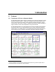
1. Introduction 1.1 Features 1.1.1 Transforms a PC into an Operator Station The CN8-SW software makes it easy for operators to use a personal computer to monitor networked Omega controllers. Linked to the controllers by an RS-485 network, the PC can be used to read process values, change setpoints and other parameters, change 1 controller mode, and monitor for alarms. CN8-SW is also ideal for quickly configuring a single controller in a lab or service department, using an RS-232 link.
CN8-SWÔ UserÕs Guide 1.1.2 Graphical Interface The CN8-SW software uses a graphical user interface and familiar point-and-click techniques. The main CN8-SW display shows PV and SP of every controller. The CN8SW system can be set up to show all controllers on the network on a single display, or only selected controllers. Any message that can be displayed on a controllerÕs front panel will also be shown on the CN8-SW display.
Introduction 1.1.3 Automated Ramp and Soak Cycles Use the CN8-SW Ramp and Soak function to configure any number of recipes consisting of any number of ramp and soak steps. These recipes are stored on the CN8-SW computer. Under the direction of CN8-SW, any controller on the network can execute your choice of recipe, even models that do not support configuration and execution of ramp and soak cycles using the controller front panel.
CN8-SWÔ UserÕs Guide 1.1.6 Local Alarms If a controller that supports the Omega Plus Protocol is in alarm, the A1 or A2 indicator on the controllerÕs Òfront panelÓ on the main display will appear to be lit (red), matching the behavior of the A1 and A2 indicators on the controller faceplate. The process value on the CN8-SW graphic display will also change color from magenta (normal) to red (alarm). As a bonus, the CN8-SW supports Òlocal alarmsÓ.
Introduction 1.3 Overview of Setup Tasks The following tasks must be performed in this sequence to use the CN8-SW application successfully with an RS-485 network. The same basic process applies to using the CN8SW application to communicate with a single controller over an RS-232 link. In the case of RS-232 links, the ÒnetworkÓ consists of only the controller and the PC. St e p Ta sk Se c t io n in t h is M a n u a l 1 Connect the controllers to the network.
CN8-SWÔ UserÕs Guide St e p Ta sk To view and change controller configuration parameters, see Section 8. To configure and run ramp/soak recipes, see Section 9. To save and load controller configuration parameter sets, see Section 10. To log PV and SP values, see Section 11.
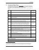
Introduction 1.4 Overview of CN8-SW Menus 1.4.1 Availability of Functions The following tables provide an overview of the functions available on the CN8-SW menus. Not all functions are available all the time. If a function is not available, its name is displayed on the CN8-SW window in gray instead of black. If a keyboard shortcut is available for a function, the shortcut appears on the menu to the right of the function name. F i le Men u Fu nct i on New Pu r p o s e Start a new CN8-SW Setup (.
CN8-SWÔ UserÕs Guide Ed i t M e n u Fu nct i on Pu r p o s e Se c t io n Operator Allows ÒSuper UsersÓ (CN8-SW Administrators) to set up operator login accounts and specify what CN8-SW features each operator will be allowed to use. 3.5 and 3.6 Password Enables operators to change their own passwords. 3.4 Vi e w M e n u Fu nct i on Pu r p o s e Se c t io n Graphic Display images of controller front panels on main CN8-SW display.
Introduction C o n t r o l l e r Me n u B e fo re y o u c a n u s e a f u n c t io n m a rk e d w ith a n a s te r is k (*) b e lo w , y o u m u s t s e le c t a c o n tro lle r o n th e m a in g ra p h ic d is p la y (o r te x t v i e w ) b y u s in g th e le f t b u tto n to c lic k o n th e c o n tro l le rÕ s im a g e (o r n a m e in te x t v ie w ). Fu nct i on Pu r p o s e Se c t io n Alarms* Configure the local alarms. 5.
CN8-SWÔ UserÕs Guide O p t i o n s Me n u Fu nct i on Pu r p o s e Se c t io n Communications Access the window used to specify PC port and communication parameters to be used by the CN8-SW software. These parameters will override (but not change) the communication settings in your operating system for the selected port. 4.
Introduction 1.4.2 Menu Convention Used in This Manual The instructions in this manual use the following format to tell you to use a particular item from a menu:
CN8-SWÔ UserÕs Guide 1-12
2. Wiring the Network and Connecting the Computer 2.1 Introduction For communication to be established between the personal computer running the CN8SW software and an Omega controller that supports Omega Plus Protocol (or the original Omega Protocol), the computer and the controller must be connected to the same network. (See 1.2 for hardware and software requirements for the personal computer.) Communication between a single controller and the CN8-SW computer can be established using an RS-232 interface.
CN8-SWÔ UserÕs Guide 2.2 Connecting Controllers and the Computer to the Network 2.2.1 Introduction The manual supplied with each controller identifies the terminals to be used for RS-232 or RS-485 communications. Consult those manuals before attempting to connect the controllers to the network. 2.2.2 RS-232 Interface Follow the instructions in the controller manual for making an RS-232 connection to the instrument.
Wiring the Network and Connecting the Computer 2.2.3 RS-485 Network If your computer is equipped with an RS-485 interface, connect to the controller network in accordance with the instructions provided with that option card. If you plan to use a serial (COM) port to connect to your network, install an RS-232-toRS-485 converter on the port (see diagram below). A suitable converter is available from Omega.
CN8-SWÔ UserÕs Guide 2-4
3. Installing the Software and Logging In 3.1 Installing the Software The CN8-SW software is supplied on a 3.5 inch diskette. Before installing the software, please read the licensing agreement. Installing the software indicates that you accept the terms of the agreement. Note that registered users are permitted to make one backup copy from the master diskette for their own use. To install the software: 1. Optional, but recommended: Close any other applications that are running. 2.
CN8-SWÔ UserÕs Guide 6. Select the drive where the software will be installed. Click on OK. The next installation window will open. 7. This window is used to specify the name of the directory in which the CN8-SW software will be installed. To accept the default name ÒMULTICOMÓ click on OK. To use a different name, type it in the box provided, then click on OK. Once you click on OK, the next installation window will open. 8.
Installing the Software and Logging In 10. To close the window and exit the installation program, click on OK. 3.2 Starting the Software Start the software as you would any other installed application.
CN8-SWÔ UserÕs Guide 3.3 Logging In to CN8-SW Using the Default Account When you start the CN8-SW application, the Operator Login Window will be displayed. By default, newly installed CN8-SW software will be set up to recognize one login account. This is user ÒMULTIÓ. The password is ÒCOMMÓ. To log in: 1. Start the CN8-SW application. 2. Select File | Login. The Operator Login window will be displayed. 3. Click on the User Id text entry box and type in MULTI.
Installing the Software and Logging In 3.4 Changing the Password for the Default Account The default account, MULTI, has permission to do everything, including create and delete other user accounts. Therefore, it is a good idea to immediately change the password for the MULTI account from COMM to something unique to your installation. Remember the new password.
CN8-SWÔ UserÕs Guide 3.5 Setting Up Operator Accounts At most sites, operators will not need permission to use all CN8-SW functions, particularly the ability to create and delete other usersÕ accounts. Therefore, it is a good idea for the CN8-SW system administrator (the person who knows the password to the MULTI account) to create login accounts for operators. 3.5.1 Permissions Available The CN8-SW system supports several permission classes.
Installing the Software and Logging In The access privilege categories grant the following permissions. Change Setpoint Change the setpoint using the Change Setpoint window (see Section 6), change the controller mode (see Section 7), and run ramp/soak recipes under the direction of CN8-SW or under the direction of the controller (see Section 9). View/Change Parameters Use the CN8-SW parameter window to view and change the parameters stored in the controllersÕ nonvolatile memory (see Section 8).
CN8-SWÔ UserÕs Guide 5. Click on the check box for each set of access privileges you want the user to have. ÒSuper UserÓ does not automatically include all the other privileges. 6. If you change your mind and want to clear a checked box, click on it again to ÒeraseÓ the check. 7. When you are satisfied with the user definition, click on OK . The window will be closed and the user definition will be saved in a .DAT file in the directory where the CN8-SW software was installed. 3.
4. Establishing Communication with Controllers 4.1 Introduction Once you have connected the controllers and the computer to the network, installed the CN8-SW software, and changed the password on the MULTI login account, you are ready to establish communication between the CN8-SW computer and the controllers on the network. You must do the following tasks.
CN8-SWÔ UserÕs Guide 4.2 Configuring Communication Parameters and Assigning Network Addresses in Controllers 4.2.
Establishing Communication with Controllers 4.2.2 Network Addresses Your goal is to assign each controller on the network a unique address between 1 and 254. This can be accomplished using the buttons and display on the front panel of the controller as described in the manual supplied with each controller. If you will have fewer than 254 controllers on the network and plan to use the CN8-SW function of automatically detecting devices on the network, use the lowest address numbers first.
CN8-SWÔ UserÕs Guide 4.3 Configuring Communication Parameters for CN8-SW System Your goal is to select the COM port to be used by the CN8-SW software. · If you do not plan to use the automatic Òfind controllersÓ option described in 4.4, then you can also specify a baud rate other than 9600 (the default) for the network. · If you do use the automatic Òfind controllersÓ feature, then the software will use 9600 baud, regardless of the baud rate specified using the Communications Setup window shown below.
Establishing Communication with Controllers 7. If necessary, change the Timeout from the default value. The Timeout is the number of milliseconds the CN8-SW system will wait to receive a reply from a controller before giving up and moving on to the next controller. 8. When the settings are correct, click on OK to save the settings and close the window.
CN8-SWÔ UserÕs Guide 4.4 Recognizing Controllers with the CN8-SW Software 4.4.1 Introduction Once you have assigned a unique network address to each controller, and set communication parameters in all controllers to their defaults, and set the CN8-SW to use the desired COM port, you are ready to enable the CN8-SW software to recognize the controllers.
Establishing Communication with Controllers · T h e s o ftw a r e p o l l s a d d r e s s e s 3 th r o u g h 2 5 4 a t 9 6 0 0 b a u d . · T h e n e tw o r k i s r e a d y t o o p e r a t e a t 9 6 0 0 b a u d . To use the automatic function: 1. Make sure all the controllers are powered up. 2. Use the front panel display and buttons on controllers that do not support the Omega Plus protocol to set their communication parameters to 9600 baud, 8 data bits, no parity, 1 stop bit.
CN8-SWÔ UserÕs Guide 8. Any message that can be displayed on a controllerÕs front panel will also be shown on the CN8-SW display. Operators can see at a glance if a controller is in standby or other special mode, and if the controller detects a problem such as an open sensor.
Establishing Communication with Controllers To return to the graphic view, select View | Graphic. When the instructions in this manual refer to the Òmain CN8-SW windowÓ, that means the graphic view.
CN8-SWÔ UserÕs Guide 4.4.3 Manually Using the Controller Menu If you want some operators to be able to see only some of the controllers on the network, you must use the manual process described here to add the controllers one operator will see, save the configuration to an .MCS file as described in 4.8, then start again, adding controllers to create a new different .MCS file for the use of a second operator.
Establishing Communication with Controllers 4.5 Deleting a Controller Any controller can be deleted from the CN8-SW setup, regardless of whether the controller was added using the automatic process described in 4.4.1 or the manual method described in 4.4.2. To delete a controller: 1. While you are logged in as MULTI (or another user with Controller Configuration Privileges) select the controller to be deleted by clicking on it (left button) on the graphic display.
CN8-SWÔ UserÕs Guide 4.6 Changing Baud Rate after Communication Has Been Established You can use the CN8-SW application to change the rate of all controllers that support the Omega Plus Protocol. As soon as you change the rate, you will lose communication with the controllers. Once all the controllers have been set to the same new rate, change the CN8-SW communication setting to match. Detailed instructions for changing the baud rate follow.
Establishing Communication with Controllers 4. To select another baud rate, use the dropdown list. 5. Click on OK. The value will be sent to the controller and the window will close. (Once the value is written to the controllerÕs non-volatile memory, communication with this controller is lost until the CN8-SW baud rate has been set to match.) 6. Repeat the process to assign the same new baud rate to every Omega Plus controller. 7.
CN8-SWÔ UserÕs Guide 4.7 Naming Controllers By default, the CN8-SW displays use a controllerÕs address as its name. However, you can assign a more meaningful name to each device. This can be done during the manual addition process described in 4.4.3. You can also assign a name (or change the assigned name) of any controller using the Controller | Configure menu function. A name may contain up to twenty letters, numbers, spaces, and special characters.
Establishing Communication with Controllers 4.11 Opening an Existing .MCS File To open a different .MCS file, use File | Open (or button on the toolbar). The operating system Open window will be displayed. Use it to select the .MCS file to open.
CN8-SWÔ UserÕs Guide 4-16
5. Configuring Local Alarms 5.1 Introduction The CN8-SW system can use the Omega Plus Protocol to read the alarm state of any controller that supports the protocol. Therefore, if an Omega Plus controllerÕs alarm parameters have been configured and the controller has detected an alarm condition, the A1 or A2 indicator on the controllerÕs Òfront panelÓ on the CN8-SW main display will appear to be lit (red), matching the behavior of the A1 and A2 indicators on the controller faceplate.
CN8-SWÔ UserÕs Guide 3. To enable local process alarm 2 (signaled using the A2 indicator on the CN8-SW display), click on the box to the left of Process Low. 4. Type in the alarm limit for each alarm. 5. Click on OK to save the changes and close the window.
6. Viewing Process Values and Changing Setpoint 6.1 Introduction For your convenience, the CN8-SW system provides several ways to view process variable and setpoint as described in 6.2 and 6.3. Any operator whose login account is configured with the appropriate privilege can use the CN8-SW system to change a controllerÕs setpoint as described in 6.4. (Instructions for changing the setpoint using ramp and soak recipes are in Section 9.
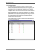
CN8-SWÔ UserÕs Guide 6.2 Viewing PV and SP in the Main Window The CN8-SW system always displays process value and setpoint for every controller in the main window, either on the graphic view or the list view. The refresh rate is dependent on baud rate, the number of controllers on the network, and the configured polling frequency and timeout (see 4.3).
Viewing Process Values and Changing Setpoint 6.3 Viewing PV and SP in a Graph The CN8-SW system allows operators to display a trend graph showing any controllerÕs SP and PV in real-time. To view the real-time trend graph: 1. While logged in as MULTI (or another user with Controller Configuration privileges), select the controller by clicking on its image in the main graphic display. The border of the controller will be highlighted. 2. Select Controller | Graph. The trend graph will be displayed.
CN8-SWÔ UserÕs Guide 6.4 Changing the Setpoint Using the Setpoint Dialog Box Any operator whose login account is configured with the appropriate privilege can use the CN8-SW system to change a controllerÕs setpoint. To change a controllerÕs setpoint: 1.
Viewing Process Values and Changing Setpoint 6.5 Configuring and Invoking the Single-Step Ramp Function The CN8-SW system provides a method to configure the single-step ramp time. The software also provides a means to invoke this single-step Ramp to Setpoint function in those Omega controllers that can use the function at times other than at startup. To configure the timer for the single step Ramp to Setpoint function: 1.
CN8-SWÔ UserÕs Guide To invoke the single step ramp function: 1. Select the controller by clicking on its image in the main graphic display. The border of the controller will be highlighted. 11 2. Select Controller | Start Recipe. The function will be invoked. (If the Recipe Option is set to ÒDisabledÓ, a confirmation message will be displayed before the PV is ramped to the setpoint; the default one minute will be used.
7. Changing Controller Mode and Using Autotune 7.1 Introduction The CN8-SW system provides operators with an easy, reliable way of changing a controllerÕs mode without using the unitÕs front panel. This ability to change mode includes placing the controller in Autotune. Before putting a controller in Autotune, be sure to read the manual supplied with the controller. Autotune will not work correctly unless you prepare the process and the controller as described in the controller manuals. 7.
CN8-SWÔ UserÕs Guide 4. To take the controller out of the mode, select the controller again. 5. Open the Controller menu. You will see the controllerÕs current special mode checked. For example, if the controller is in Standby, then the menu will show Ö Standby. Click on the checked mode to take the controller out of that mode.
8. Viewing and Changing Controller Configuration Parameters 8.1 Introduction The CN8-SW system permits any operator with View/Change Parameter privileges to access parameter values stored in each controllerÕs memory. The Omega Plus Protocol supports viewing and changing all parameter values over the network. These Omega Plus controller values are read and stored in non-volatile (permanent) memory.
CN8-SWÔ UserÕs Guide Sometimes it is possible to type a value in the CN8-SW window, but the value will not be accepted by the controller. The value will not be accepted if the controller hardware does not support use of the parameter. You will be informed by a CN8-SW message that the controller will not accept the input. The displayed values are currently stored in the controller.
9. Configuring and Running Ramp and Soak Recipes 9.1 Introduction Use the CN8-SW Ramp and Soak function to configure any number of recipes consisting of any number of ramp and soak steps. These recipes are stored on the CN8-SW computer. Under the direction of CN8-SW, any controller on the network can execute your choice of recipe, even models that do not support configuration and execution of ramp and soak cycles using the controller front panel. Instructions for configuring these recipes are in 9.2.
CN8-SWÔ UserÕs Guide 9.2 Configuring CN8-SW Recipes 9.2.1 Creating a New Recipe To create a new recipe to be run on any controller under the direction of the CN8SW system: 1. While logged on as MULTI (or another user with View/Change Parameter privileges), select Ramp/Soak | New. The Recipe Editor window will be displayed. You will use the Ramp Time, Soak Level, and Soak Time boxes to configure each step, then use the Append Step button to add the step to the end of the recipe in the large white box.
Configuring and Running Ramp and Soak Recipes 6. Enter a Holdback value of at least 1, or disable holdback. 12 7. Enter the Ramp Time, Soak Level (setpoint), and Soak Time for a recipe step in the 13 boxes provided. 8. Click on Append Step. The step will be added below the steps already in the recipe box. The Ramp Time, Soak Level, and Soak Time boxes will be cleared in preparation for entering your next step. 9. Repeat Steps 7 and 8 as many times as you want. 10. Save the .
CN8-SWÔ UserÕs Guide 11. To delete a step from the recipe as shown in the white box, click on the step to select it. The values of the selected step will be displayed in the Ramp Time, Soak Level, and Soak Time boxes. Click on Delete Step. The step will be removed from the recipe. 12. To edit a step, select it. Its values will be displayed in the Ramp Time, Soak Level, and Soak Time boxes. Make your changes, then click on Edit Step. The new values will replace those in the selected step. 13.
Configuring and Running Ramp and Soak Recipes 9.3 Running CN8-SW Recipes 9.3.1 Starting to Run a Recipe To run a CN8-SW Ramp/Soak recipe: 1. While logged in as MULTI (or another user with View/Change Parameter privileges), select Ramp/Soak | Run. The Open Recipe window will open. 2. Select the .rcp file to be run and click on OK. The Run Recipe Controller Selection window will open. 3.
CN8-SWÔ UserÕs Guide 9.3.2 Holding (Pausing) Recipe Execution To hold execution of a CN8-SW recipe: 1. While logged in as MULTI (or another user with View/Change Parameter privileges), select Ramp/Soak | Hold. The Recipe Control window will open. 2. The window lists all the recipes being run under the direction of CN8-SW. A recipe may appear on the list in the left pane more than once. This means that you started to run the recipe on different controllers (or sets of controllers) at different times.
Configuring and Running Ramp and Soak Recipes 9.3.3 Resuming Recipe Execution To resume execution of a ÒheldÓ recipe: 1. While logged in as MULTI (or another user with View/Change Parameter privileges), select Ramp/Soak | Resume. The Recipe Control window will open. 2. The window lists all the recipes being run under the direction of CN8-SW. A recipe may appear on the list in the left pane more than once.
CN8-SWÔ UserÕs Guide 9.3.4 Stopping Recipe Execution To stop execution of a CN8-SW recipe: 1. While logged in as MULTI (or another user with View/Change Parameter privileges), select Ramp/Soak | Stop. The Recipe Control window will open. 2. The window lists all the recipes being run under the direction of CN8-SW (both active and held). A recipe may appear on the list in the left pane more than once.
Configuring and Running Ramp and Soak Recipes 9.4 Configuring Controller Ramp and Soak Parameters To configure a recipe using the recipe parameters of Omega Plus controllers which support this function: 1. While logged in as MULTI (or another user with View/Change Parameter privileges), select the controller by clicking on it in the main graphic display. 2. To display the present values of all parameters stored in the controllerÕs non-volatile memory, select Controller | Parameters.
CN8-SWÔ UserÕs Guide 4. To enable Multi-Step Ramp, click on the white dot (Òradio buttonÓ) next to it. A black dot in the circle indicates that the function has been selected. The gray values in the Multi-Step Ramp panel, and in the the Holdback Band, Termination State, and Repeats entry boxes will become black, indicating that they can be edited. The Power Fail Resume and Continuous Repeat labels will also become black, indicating that these options are available for selection.
Configuring and Running Ramp and Soak Recipes 8. To edit a step, click on it to select it, then click on Edit Step. 9. Enter the Ramp Time, Soak Level (setpoint), and Soak Time for a recipe step in the 17 boxes provided. 10. Repeat Steps 8 and 9 until the recipe meets the needs of your application. 11. If you want to save this recipe to an .RS file on a drive accessible to the CN8-SW computer, use the Save As button. A window will open in which you can specify the filename and directory.
CN8-SWÔ UserÕs Guide 9.5 Running Controller Ramp and Soak Cycles To run a multi-step ramp and soak recipe based on the values stored in the controller: 1. Select the controller by clicking on its image in the main graphic display. The border of the controller will be highlighted. 2. Select Controller | Start Recipe. The function will be invoked. Note that if the Recipe Option is set to ÒSingle-Step RampÓ or ÒDisabledÓ, then the multi-step ramp function is not available.
10. Storing and Loading Controller Configurations 10.1 Introduction All the configuration parameter values stored in non-volatile memory in a controller that supports Omega Plus Protocol can be saved to the PC and loaded to the same or different controllers. Backing up a unique controller configuration on a PC or removable medium is always prudent. If a controller is damaged later and must be replaced, the custom configuration can be loaded quickly to a spare controller, minimizing down time.
CN8-SWÔ UserÕs Guide 10.2 Storing Configuration To save an Omega Plus controllerÕs configuration on the CN8-SW computer: 1. While logged in as MULTI (or another user with View/Change Parameter privileges), select the controller by clicking on it in the main graphic display. 2. To display the present values of all parameters stored in the controllerÕs non-volatile memory, select Controller | Parameters. The parameter window for that controller will open. By default, the Input ÒtabÓ will be on top. 3.
Storing and Loading Controller Configurations 4. To save the parameter set in a .PRF file, click on Save As. The Save Parameter Set window will open. Use it to enter a filename (with a .PRF file extension) and to specify a destination directory. (To save the parameter set to a file with the same name as the controller, click on Save. The file will be saved in the same directory where the CN8-SW software was installed.) 5. As the save progresses, a status window will be displayed.
CN8-SWÔ UserÕs Guide 10.3 Loading Configuration To save an Omega Plus controllerÕs configuration on the CN8-SW computer: 1. While logged in as MULTI (or another user with View/Change Parameter privileges), select the controller by clicking on it in the main graphic display. 2. To display the present values of all parameters stored in the controllerÕs non-volatile memory, select Controller | Parameters. The parameter window for that controller will open. By default, the Input ÒtabÓ will be on top. 3.
Storing and Loading Controller Configurations 4. To load a parameter set to the selected controller, click on Load. The Open Parameter Set window will open. 5. Select the name of the .PRF file to be loaded to the controller and click on OK. The parameter values stored in the file will be written to the controller. 6. As the load progresses, status windows will be displayed. When no more status windows are displayed, the load has completed successfully.
CN8-SWÔ UserÕs Guide 10-6
11. Logging PV and SP Values 11.1 Introduction The CN8-SW application supports optional logging of SP and PV values for all controllers at configurable intervals. Logs are saved in ASCII text files with comma-separated-value format. These files can be viewed, printed, and manipulated with other applications, such as word processing and spreadsheet software. 11.2 Turning On the Logging Function To turn on the logging function: 1.
CN8-SWÔ UserÕs Guide 5. To append new data to the old file, click on Yes. To overwrite the old file, click on No. This will result in the old data being lost. 11.3 Viewing and Printing Log Files The log files are ASCII text file with comma-separated values. To view and print the files, use any text editor (such as WordPad) that will retain the line breaks. 11.4 Turning Off the Logging Function To turn off the logging function: 1.
12.
CN8-SWÔ UserÕs Guide recipes (controller) configuring, 9-9 running, 9-12 recipes (CN8-SW) configuring, 9-2 running, 9-5 recognizing controllers, 4-6, 4-10 Repeats field, 9-2, 9-10 Resume function, 9-7 RS file, 9-11 RS-232 interface, connecting controller and computer, 2-2 RS-485 interface, connecting controllers and computer, 2-3 Run Recipe Controller Selection window, 9-5 CN8-SW Setup files, 1-7, 4-8, 4-11 closing, 4-14 creating, 4-14 opening, 4-15 saving, 4-14 Multi-Step Ramp, 9-10 N naming controllers,