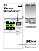
MADE IN USA User’s Guide Shop on line at Pressure/Temp http://192.168.1.200 Pressure/Temp ® Alarm SP1(above)=0095.0 F Alarm SP2(below)=0070.0 F Temperature 78.3 F Archives_Inactive 122 Pressure 1000.3 1200 9/Div 80/Div 32 Mon Jul 24 09:42:10 PST 2006 hPa ® www.omega.com e-mail: info@omega.com For latest product manuals www.omegamanual.
® ® OMEGAnet® On-Line Service www.omega.com Internet e-mail info@omega.com Servicing North America: USA:SS SS SS One Omega Drive, P.O. Box 4047 Stamford CT 06907-0047 TEL: (203) 359-1660SS FAX: (203) 359-7700 e-mail: info@omega.com Canada:: S SS SS SS 976 Bergar Laval (Quebec) H7L 5A1 TEL: (514) 856-6928SS e-mail: info@omega.
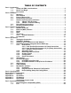
TABLE OF CONTENTS Part 1: Introduction 1.1 Safety and EMC Considerations........................................................................2 1.2 Before You Begin ................................................................................................2 1.3 Description ..........................................................................................................2 Part 2: Hardware 2.1 Mounting .............................................................................................
LIST OF FIGURES: Figure 1.1 Figure 2.1 Figure 2.2 Figure 2.3 Figure 2.4 Figure 2.5 Figure 2.6 Figure 2.7 Figure 3.1 Figure 3.2 Figure 3.3 Figure 4.1 Figure 4.2 Figure 4.3 Figure 4.4 Figure 4.5 Figure 4.6 Figure 4.7 Figure 4.8 Figure 4.9 Figure 4.10 Figure 4.11 Figure 4.12 Figure 4.13 Figure 4.14 Figure 4.15 Figure 4.16 Figure 4.17 Figure 4.18 iServer and iLD Big Display on the Ethernet Network........................3 Mounting ................................................................................
NOTES, WARNINGS and CAUTIONS Information that is especially important to note is identified by the following labels: • NOTE • WARNING or CAUTION • IMPORTANT • TIP NOTE: Provides you with information that is important to successfully setup and use the iServer. CAUTION: Tells you about the risk of electrical shock. CAUTION: Risk of danger. Tells you of circumstances or practices that can effect the instrument’s functionality and must refer to accompanying documents. TIP: Provides you helpful hints.
PART 1 INTRODUCTION 1.1 Safety and EMC Considerations Refer to the CE Approvals Section. EMC Considerations • Whenever EMC is an issue, always use shielded cables. • Never run signal and power wires in the same conduit. • Use twisted-pair wires for signal connections. • Install Ferrite Bead(s) on signal wires close to the instrument if EMC problems persist. Failure to follow all instructions and warnings may result in injury! 1.
Award-winning Technology. The iServer is simple to install and use. It features award winning technology that requires no special software except a Web browser. The iServer connects to an Ethernet Network with a standard RJ45 connector and sends data in standard TCP/IP packets. It is easily configured with a simple menu using a Web browser and can be password protected.
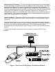
PART 2 HARDWARE 2.1 Mounting 3.55 [90.2] 3.05 [77.5] 2.42 [61.6] 2.00 [50.8] Position unit where required. Mark and drill holes as required. If unit is to be mounted on a flat surface, you may take the bottom rubber feet off the unit. It is recommended that you ground your unit by wrapping a wire around the mounting tab screw and tightening a lock washer so that it embeds itself into the metal of the mounting tab. Or by connecting a wire to the Return/Ground position of the relay connector, see Figure 2.
2.3 Parts of the iServer Unit iServer RJ45 interface Side or Bottom Wire Entry for Relay Connector iServer Reset Button iServer LEDs 8 ACTIVITY NETWORK LINK DIAGNOSTICS AND STATUS 1 ETHERNET RESET Removable Plug Connector for Relays under the Cover 6 16 Digit LCD Display Probe Handle Clip Flash Memory Card 1 UNITS TIME STBY BKLT Mounting Tabs BAROMETER/TEMPERATURE Buttons Flash Memory Card Reset Button 9-12 Vdc DB9 Connector dc Power Input Figure 2.3 Parts of the iServer Unit Table 2.
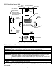
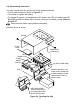
2.4 Disassembly Instruction You may need to open the unit for one of the following reasons: • To wire relay connector. (Refer to Figure 2.7) • To connect or replace the battery. • To change S5 jumper. In the absence of AC power, and if S5 is installed, the LCD Backlight and iServer Board will be on and running on the battery power. Refer to Section 2.7. Disconnect the power supply before proceeding. Remove Cover as shown.
2.5 Network Communication Interfaces 2.5.1 10Base-T RJ-45 Pinout Pin 1 2 3 4 5 6 7 8 The 10BASE-T Ethernet network (RJ45) system is used in the iServer for network connectivity. The 10 Mbps twisted-pair Ethernet system operates over two pairs of wires. One pair is used for receiving data signals and the other pair is used for transmitting data signals. This means that four pins of the eight-pin connector are used.
PART 3 NETWORK CONFIGURATION 3.1 Network Protocols The iServer can be connected to the network using standard TCP/IP protocols. It also supports ARP, HTTP (WEB server), DHCP, DNS and Telnet protocols. 3.2 Ethernet (MAC) Address MAC (Media Access Control) address is your computer's unique hardware number. When you're connected to the LAN from your computer, a correspondence table relates your IP address to your computer's physical (MAC) address.
3.3 DHCP DHCP, Dynamic Host Configuration Protocol enables individual computers or devices to extract their IP configurations from a server (DHCP server). If the DHCP is enabled on your iServer, as soon as the iServer is connected to the network, there is an exchange of information between DHCP server and the iServer. During this process the IP address, the Gateway address, and the Subnet Mask will be assigned to the iServer by the DHCP server.
3.5.1 Default IP Address The iServer is shipped with a default IP address set to 192.168.1.200 and Subnet Mask of 255.255.255.0. If you are going to use a Web browser or Telnet program to access the iServer using its default IP address, make sure that the PC from which you’re establishing the connection has an IP address that is in the same range as the iServer’s IP address (192.168.1.x, where x can be any number from 1 to 254. Your PC’s IP address cannot be the same as the iServer’s IP address).
PART 4 OPERATIONS This iServer can be used and configured in several ways, depending on user’s preference and network setup. It can be configured using a Web browser, like Netscape or Internet Explorer. It can also be configured using NEWPORT’s iCONNECT Configuration Software. If DHCP and DNS servers are used, the connection is very simple, no need to find the right IP address or watch for network conflicts, these are all done for you by your network DHCP and DNS server.
4.1 iCONNECT Software The iServer may also be assigned an IP Address by using the iCONNECT software. a) Download the iCONNECT software from the website listed in this manual. b) Install iCONNECT software on a networked PC. This software is compatible with Windows 95, NT, 2000, and XP. c) Use iCONNECT to assign an IP address to the iServer and access its web pages for configuration. You can also use any standard web browser to access the iServer’s web pages.
4.2 Setting a New IP Address over the Network Besides using the iCONNECT software, you may use the iServer’s default IP address to access it and assign a new IP address to it. The iServer is shipped with a default IP address of 192.168.1.200 and Subnet Mask of 255.255.255.0. You can configure your PC’s Network connection with an IP address that is in the same range as the iServer’s IP address (192.168.1.x) and connect to the iServer using a crossover network cable between your PC and the iServer.
4.3 Setup and Operation using the iServer Web Page • Start your web browser. • From the browser you type http://eisxxxx using the last four-digits from the MAC address label located on the device if DHCP and DNS are used. If a static IP address is used, then simply type http://x.x.x.x, where x.x.x.x is the iServer’s IP address. • The Home Page, shown in Figure 4.5, will be displayed. iServer Home Page http://192.168.1.
4.3.1 Read Sensor • Click on Read Sensor . In a few seconds the following page (Figure 4.7) will appear with all default values of 100.00. Then the actual readings of Temperature and Barometric Pressure will be displayed. • This page automatically updates the Temperature and Barometric Pressure values. • Click on Main Menu to return to Home Page.
4.3.1.2 Java Runtime Environment 1.5 (5.0) Setup instructions 1. Go to your computer's Control Panel. Open the Java Plug-in 2. Click on "Settings" & "View Applets" in the "General" tab. 3. Select the "Settings" button on the General Tab Un-check the "Enable Caching" box. Then close dialog box to show the General Tab again 4. Select the "Network Settings" button on the General Tab. Proceed to the Browser tab. Follow the Browser Proxy Selection instructions below.
4.3.2 Adjustable Chart • Click on Chart , the following page (Figure 4.8) should appear. The Java™ Applet graph displays Temperature and Barometric Pressure and can be charted across the full span (-40 to 123ºC) or within any narrow range (such as 20-30ºC). The time-base can display one minute, one hour, one day, one week, one month or one year.
4.3.3 Retrieving Data from Flash To retrieve and graph the data that is stored in the Flash Memory, you have two options: OPTION 1: You can use the iServer’s WEB interface to chart the data stored in the flash memory. 1. Click on the “Chart” button located on the Server Home Page, see Figure 4.5. 2. Select a time interval of Day, Week, Month or Year (Minute and Hour are not selectable for data retrieval). 3.
4.3.4 Access Control This section describes the "Access Control" page of the iServers’s Web interface. This page allows the users to set up the network and security parameters of the iServer. At the initial entrance to the “Access Control” page you will be prompted for the LOGIN Password (see Figure 4.6) prior to an ADMINISTRATOR Password. Access Control http://192.168.1.200 The DHCP can be enabled by setting the dip switch number 3 to ON position.
4.3.5 Configuration Setting up the Flash Memory Card can be done in the Configuration page. From the Home Page Menu click on Configuration to get to the page (see Figure 4.11). General Description of the Configuration page: There are two general sections “Flash Card Memory” and “Server”. Flash Card Memory consists of the following titles: Real Time Clock (RTC), Title, Alarm Setup, and Flash Recording. Server consists of Terminal Server and Remote Access.
4.3.5 Configuration (continued) http://192.168.1.200 Sensor Name Temperature Pressure Remote Format T0000.00 P00000.0 Remote End Char (HEX) 0D 0D Offset 0000.0 0000.0 Click on Device No. on the left to modify Sensor Parameters. 07/24/2006 Flash Card Pre-Recorded AC Power On 0095.0 nnnn.n Pressure/Temp 0070.0 nnnn.n Sensor Units: F:hPa Wrap Status/RTC/Alarm 07/25/2006 05:00:00 07/28/2006 19:00:00 Command 5 Figure 4.
B) Real Time Clock RTC Date and Time: The formats are mm/dd/yyyy and hh:mm:ss. The exact formats are required otherwise an error message will appear in the Title box. Note: time is military time/24 hour based. Adjust RTC Only: If checked, the clock will be updated and nothing else, provided that “Activation” is set to “Status/RTC/Alarm”. To verify the clock, set the “Activation” to “Configuration”, click Update button, then set “Activation” to “Status/RTC/Alarm” and click Update button one more time.
F) Flash Recording Title: Editable field with up to 16 characters long. The given name will display as a title on the Chart and Read Sensor pages either for the real-time data or the stored data. Sensor Unit: The unit of temperature either in degree Fahrenheit F or degree Celcius C for each type of barometric pressure unit hPa, inHg or mmHg.. LCD/PWR: The selections are “ON ”, “OFF ”, and “UPS”. Selecting “OFF” will cause the LCD to turn off during a power outage, provided the battery is connected.
NOTE 2: Downloading data and recording can not be done at the same time. While downloading data, the writing process to the flash memory will be internally disabled while the data is being read from the memory flash. For small amounts of data to be retrieved (1 Day or 1 Week), this is not a significant interruption in the recording data. However, for large amounts of data (1 Month or 1 Year) it may take 4 to 8 minutes to download the data.
Port: (default 2000) is the default TCP port number for the port to which the sensor is connected. Ports 1000 (used for HTTPget, refer to Section 4.5), 2002, 2003, and 2004 are reserved for internal use. Terminal Server usually describes a device that exchanges data between Ethernet/TCPIP networks and RS-232/RS-485 systems. With this iServer, the data is obtained digitally from the sensor (irrelevant to RS-232 or RS-485 interface) and can be accessed from anywhere on the network.
4.3.6 Sensor Parameters • In the first column of Configuration page (Figure 4.11), click on No. 1 to view and modify the Sensor Parameters page for Temperature. Sensor Parameter http://192.168.1.200 You may type any ASCII characters in the first three boxes, but you must delete the leading spaces. SENSOR PARAMETER Device No. 1 Device Name: Temperature Remote Display Format: Remote End Char (HEX) 0X: Offset: 0000.0 T0000.00 0D C Update Reset Cancel Main Menu Figure 4.
4.4 Telnet Setup Set the Number of Connections to 1-5 other than 0, using telnet simulation program connect to iServer. In continuous mode, the telnet teminal will receive continuous messages from the iServer. In command mode, the command can be sent to query the iServer and get a response back. Refer to Figure 3.3 Send remote reset: Telnet port 2002 will bring a terminal for admin password. After typing the password and following with the end character, the message Admin.
4.5.1 HTTPGET using Port 1000 You can setup and read the information from the iServer by using the HTTPGET program. The following program can be used to read data from the embedded server firmware by using TCP port 1000. The command string is sent to this TCP port, then the response can be read back from the same socket. The Httpget.exe file is used to setup and read information from the iServer.
4.5.2 HTTPGET and ARP to setup Device IP Address Use the iCONNECT software, which may be downloaded from our website, to do these IP changes whenever possible. Use ARP first to assign the mac address to a static IP address in computer arp table by this command: apr –s 192.168.1.200 00-03-34-00-00-06-b6 Then use the following command to assign new IP to the device: Httpget –r –S "00000000" 192.168.1.200:1 where: “00000000” is admin. password. If the password is wrong, the unit will ignore the new IP.
4.6 ARP Protocol ARP is the Internet layer protocol responsible for matching or obtaining the MAC (hardware) address that corresponds to a particular IP address. The ARP command allows the user to view the current contents of the ARP cache of the local computer (residing on the same network). Microsoft includes the ARP.EXE utility for viewing and modifying the ARP cache with its Windows products.
4.7 iLOG Software The iLOG software can be used only with NEWPORT Electronics instruments. This is an Excel application software that can log temperature and barometric pressure from an iServer over the Ethernet or the internet. a) b) c) Download the iLOG software from the website listed in this manual. Install iLOG software on a networked PC. This software is compatible with Windows 95, 98, NT, 2000, and XP. For complete information of how to use the iLOG software, click on the HELP button. Figure 4.
4.8 Mail Notifier Software The Mail Notifier Software can be used only with NEWPORT Electronics instruments. For complete information of how to use the Mail Notifier software, click on the Help menu of the main window. The Mail Notifier software generates email notifications for alarm conditions. Users can be notified automatically of alarm conditions monitored via internet connections throughout the world.
4.8.2 Program Options Setup and Configuration Complete program setup requires: • Entering a recipient for the email • Specifying connection details to MAPI services. • Defining alarms for devices, and selecting how and when the email will be active. Figure 4.17 iServer Mail Notifier Profile Setup The “Send To” tab contains a field to specify an email address to which alarm notifications will be sent (i.e. the recipient). Only one entry is permitted, in the address field.
4.8.3 Device Setting and Configuration Device setup requires: • Entering the IP address for iServer device (for example 192.168.1.200). • Specifying Socket number (1000 or 2000 depending on iServer settings). • Defining RS485 Unit # interface address (1 to 199). Enter "0" for RS232 interface or for iServer. • Entering Reading command. Normally set to SRT to obtain reading from the devices.If you want to change this setting, refer to HTTPget Section 4.5.
PART 5 SPECIFICATIONS Processor: Enhanced 8051, 22 MHz Memory: 512 Kbytes Flash, 16 Kbytes SRAM Memory Data Flash Card: 2 Mbytes or 2 months of data storage at 10 second logging intervals, or 1 year at 1 minute logging intervals. Atmel# AT45DCB002 Optional Flash Cards: 4 Mbyte (2 years at 1 minute intervals) 8 Mbyte (4 years at 1 minute intervals) Relay Outputs: Two relays 1.
PART 6 FACTORY PRESET VALUES PRESET PARAMETERS Network Interface: IP Address Gateway Address Subnet Mask Device Host Name Login Password Admin Password DHCP Flow Control End Character Terminal Server: Server Type Number of Connections Port # Server Mode Remote Access (Tunneling): Remote Access Remote Port Remote IP Address LCD Backlight FACTORY DEFAULTS 192.168.1.200 0.0.0.0 255.255.255.
APPENDIX A GLOSSARY User of this manual should be familiar with following definitions: ARP (Address Resolution Protocol) is a protocol for mapping an Internet Protocol address (IP address) to a physical machine address that is recognized in the local network. For example, the IP address in use today is an address that is 32-bits long. In an Ethernet local area network, however, addresses for attached devices are 48-bits long.
Appendix B IP Address An IP address is a unique 32-bit address assigned to a computer and includes: • A network ID number identifying a network. • A host ID number identifying a computer on the network. All IP addresses have been divided into three smaller groups (classes) A, B and C • Class A addresses have 8-bits of network ID and 24-bits of host ID. They can support a large number of hosts, approximately 2 = 16,777,216 computers per network. The IP addresses range in binary from 00000001.xxxxxxxx.
Appendix C IP Netmask IP Netmask or Subnet Mask is a 32-bit pattern of ones and zeros used to determine network portion of an IP address from the host portion of the IP address. Subnet mask is a network ID that is created by borrowing bits from host portion of IP address and using them as part of a network ID. The table below shows a default subnet mask for address Classes A, B, and C.
Appendix D ASCII Char NUL SOH STX ETX EOT ENQ ACK BEL BS HT LF VT FF CR SO SI DLE DC1 DC2 DC3 DC4 NAK SYN ETB CAN EM SUB ESC FS GS RS US SP ! " # $ % & ‘ ( ) * + , .
Appendix D / 47 0 48 1 49 2 50 3 51 4 52 5 53 6 54 7 55 8 56 9 57 : 58 ; 59 < 60 = 61 > 62 ? 63 2F 30 31 32 33 34 35 36 37 38 39 3A 3B 3C 3D 3E 3F ASCII Chart Continuation 00101111 o 111 p 00110000 112 q 00110001 113 00110010 r 114 00110011 s 115 00110100 t 116 00110101 u 117 00110110 v 118 00110111 w 119 00111000 x 120 y 00111001 121 00111010 z 122 { 00111011 123 | 00111100 124 } 00111101 125 00111110 ~ 126 00111111 DEL 127 6F 70 71 72 73 74 75 76 77 78 79 7A 7B 7C 7D 7E 7F 01101111 01110000 01110001 0
PART 7 APPROVALS INFORMATION 7.1 CE APPROVAL This product conforms to the EMC directive 89/336/EEC amended by 93/68/EEC, and with the European Low Voltage Directive 72/23/EEC. Electrical Safety EN61010-1:2001 Safety requirements for electrical equipment for measurement, control and laboratory.
WARRANTY/DISCLAIMER OMEGA ENGINEERING, INC. warrants this unit to be free of defects in materials and workmanship for a period of one (1) year from the date of purchase. In addition to OMEGA’s standard warranty period, OMEGA Engineering will extend the warranty period for one (1) additional year if the warranty card enclosed with each instrument is returned to OMEGA. If the unit malfunctions, it must be returned to the factory for evaluation.
Where Do I Find Everything I Need for Process Measurement and Control? OMEGA…Of Course! Shop on line at omega.