
User's Manual

4
1.1.3. SOFTWARE INPUTS
a. Data Request to request an XPC update.
For example, upon Data Request on the A axis, the following operation is
done:
XPC
A
⇐ IPC
A
Notes:
1. Data Request may be applied on a single axis, or (all at once) on:
axes pair (A+B or C+D), or all four axes.
2. Besides this
software Data Request, there is also a hardware (real-time)
Data Request applied on all four axes, as described in section 1.2.1 / ii.
b. Reset to clear the IPC.
For example, upon Reset on the A axis, the following operation is done:
IPC
A
⇐ 0
Note: Reset may be applied on a single axis, or (all at once) on an
axes pair (A+B or C+D).
1.2. CARD'S HARDWARE I/O
1.2.1. HARDWARE INPUTS
i. Inputs #1–#10: Ten general inputs (reflected by software outputs).
ii. Input #11: Data Request to request all XPC’s update:
Upon this hardware Data Request, the following operations are done (all at once):
XPC
A
⇐ IPC
A
; XPC
B
⇐ IPC
B
; XPC
C
⇐ IPC
C
; XPC
D
⇐ IPC
D
.
In other words – this Data Request is a hardware real-time equivalent to the software
function RequestPositionCounter (CardHandle, Encoder4, OutputsMirror
)
(this is function #26 in section 3.5.5.) .) The minimal pulse width should be 20 ns;
the ‘snapshot’ is produced when the pulse goes low
.
1.2.2. HARDWARE OUTPUTS
a. Three general outputs (reflecting software inputs).
b. Four outputs of the Event Signals, as described in section 1.1.2 / ii. The user
may define these outputs to be held until he sends an explicit "Clear" request.
2. CARD'S HARDWARE
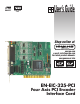
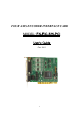
The EN-EIC-325-PCI uses the PCI bus of the PC.
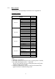
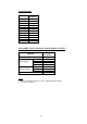
2.1. DATA BUS and ADDRESS BUS
* The Data bus is 32 bits connected to the PCI.
* The Address bus is 32 bits (I/O access only, on lower 1MB mode).
* The Address access space is 16 bytes, located from Base Address to
Base Address
+ 15. The Base Address is allocated by the system each PC
power-up.
* Bus controls – see the PCI standard version 2.1.