
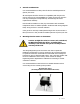
- Omega Sensor User's Guide


pg. 5 of 29
proven design minimizes zero drift while maintaining fast response and
linear outputs with virtually no maintenance.
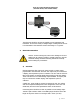
Flow is measured using a miniature turbine wheel similar in size to a U.S.
dime (16 mm diameter, 0.75 mm thick). The micro-turbine wheel is
supported on a very small sapphire shaft that is held in position by two
sapphire bearings.
As flow passes through the sensor, a precision machined nozzle directs the
gas onto the very small teeth of the micro-turbine wheel. This causes the
wheel to spin at a speed proportional to the volumetric flow rate.
The micro-turbine wheel has alternating white and black sections evenly
spaced on one side of the wheel. An infrared light beam is directed onto
the wheel. As the wheel rotates the infrared beam is reflected off each
white section. The reflected beam is detected by a phototransistor that
converts the reflections into electrical pulses. As the wheel spins faster the
pulse rate increases. Processing circuitry provides analog and/or pulse
output that are linearly proportional to the volumetric flow rate
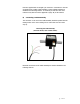
When the wheel stops (under zero flow conditions), no pulses are
generated. Consequently, zero drift is not possible and zero adjustments
are never required.
Every unit is supplied with a calibration certificate detailing the results
obtained during calibration. Units are calibrated using AIR as the reference
media. Flowing gases with different physical characteristics may effect the
calibration.
B.
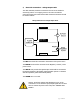
Installation
Caution: Do not exceed the pressure, temperature or
power operating ranges detailed in the SPECIFICATIONS
section of this manual. Omega Engineering shall not be
liable for any damage or injury caused by incorrect
operation of their products.