
- Omega Sensor User's Guide


pg. 12 of 29
C.
Operation
CAUTION: DO NOT FLOW ANY LIQUID THROUGH A GAS
FLOW SENSOR OR FLOW METER. THIS WILL SERIOUSLY
EFFECT THE PERFORMANCE AND VOID THE WARRANTY.
1. Start Up
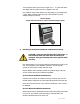
Before applying power to the unit check all tubing and electrical
connections. Once correct installation is verified switch on the power.
2. Flow Readings
The FLR 1000 Series for gases provide a 0-5VDC output proportional to
the volumetric flow rate.
The FLR 1000-D and FLR 1000-BR-D series feature an integral 3.5 digit
display that provides a local flow reading and a 0-5VDC analog output
proportional to the volumetric flow rate.
Each unit is factory calibrated for a specific flow range. The flow range is
shown on the unit’s label and calibration certificate. Units are calibrated
using AIR as the reference media unless otherwise noted. Calibrations are
carried out with the mounting feet horizontal on a flat horizontal surface.
a) 0-5VDC Analog Outputs
By monitoring the voltage output signal it is possible to determine the flow
rate of the gas. Units are configured so that an output signal of 5.0VDC is
provided when the maximum flow (i.e. Full Scale flow) is passing through
the unit. The output signal is linear and scaleable enabling calculation of
flow rates within the sensor’s range.
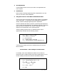
For example:
For a flow range of 100-500ml/min:
At 500ml/min the output signal would be 5VDC
If the output signal were 3.5VDC then the flow rate would be:
(500 ÷ 5) × 3.5 = 350ml/min
If the maximum flow rate is exceeded non-linear and inaccurate readings
will result.
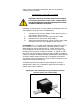
b) Units With an Integral Display
The FLR 1000-D and FLR 1000-BR-D series features an integral 3 ½ digit
LCD display. This is configured to read in ml/min for flow ranges up to