
- Omega Sensor User's Guide


pg. 11 of 29
d) Using a 0-5VDC Output Power Adapter Package.
An optional 0-5VDC Output Power Adapter Package is available for use
with the FLR 1000 series (not the FLR 1000-ST-I). This consists of a power
source (115VAC or 230VAC) and cable assembly with pig-tail (soldered
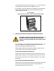
wire) ends for the signal output. This should be assembled as shown in
the following diagram.
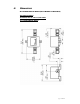
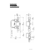
Connecting the Power Adapter to the Flow Sensor
(FLR 1000 shown, other models similar)
The 0-5VDC analog output may be connected to a display, data acquisition
system or voltmeter with a minimum load of 2.5 kΩ (kilo ohms).
The YELLOW wire of the cable assembly provides the 0-5VDC signal
output and should be connected to the positive terminal of the display,
data acquisition system or voltmeter.
The GREEN wire is not used.
The WHITE wire of the cable assembly is the signal negative and should
be connected to the negative (ground) terminal of the voltmeter, display
or data acquisition system.
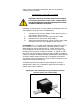
Caution: Avoid high voltage static discharges to any of the
connections. Do not short the output signal wires or allow them
to contact the power wires at any time. DAMAGE WILL RESULT!