
User's Manual
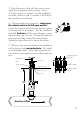

alignment rod
sensor flange
process pipe (top view)
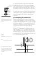
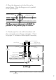
The flow sensor alignment rod MUST be
parallel to the process pipe as shown.
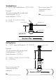
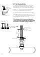
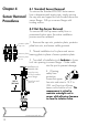
direction of flow
sensor flange
18 inch threaded rods
13.75 in.
process pipe (side view)
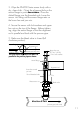
direction of flow
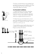
alignment rod
Upper hex nuts
(3/16 x 1/4-20)
1/4 in. lock washers
Brass sensor nut
Bleed valve
lower hex nut and
jam nuts
11
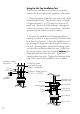
3. Wipe the FP-6000 Series sensor body with a
dry, clean cloth. Orient the alignment hole on the
sensor flange to point downstream. Place the
slotted flange over the threaded rods. Lower the
sensor into fitting until the sensor flange rests on
the lower hex and jam nuts.
4. Secure the sensor with lock-washers and upper
hex nuts on the top of the flange. Before tighten-
ing, align the sensor flange so that the alignment
rod is parallel and level with the process pipe.
5. Make sure the bleed valve is closed (full
clockwise position).