
User's Manual

6
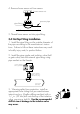
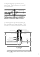
4. Open the isolation valve and insert the drill
through the valve and cut the sensor clearance
hole. After the hole is cut, withdraw the drill from
the isolation valve and close the valve. Remove
the drilling machine per manufacturer's instructions.
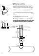
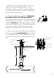
5. Install brass sensor nut/bleed valve into the top
of the isolation valve. Make sure the bleed valve
clears the handle of the isolation valve during
operation.
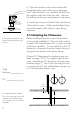
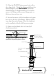
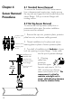
3.5 Calculating the H Dimension
Before installing the sensor some critical dimen-
sions must be established. The rotor shaft must be
located 10% inside the pipe I.D. to insure accurate
calibration capability. To accomplish this, the "H"
dimension is measured from the outside surface of
the pipe to the bottom of the sensor flange.
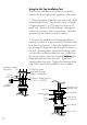
Nominal "H" dimensions for standard pipes are
listed on page 18-19. For irregular pipe dimen-
sions, calculate the "H" dimension using the given
formulas (page 7). The 6 inch ruler may be used
to measure the I.D. and wall thickness of pipes up
to 5 inch (standard sensors only).
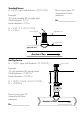
For standard sensor installa-
tions, the ruler may be used to
measure wall thickness and
I.D. of pipes up to 5 inches in
diameter.
Wall
thickness:____________
I.D.: ________________
For Hot-Tap installations, we
assume pipe dimensions are
known
A
B
1
2
3
4
5
6
1
2
3
4
5
A
B
1
2
3
4
5
6
1
2
3
4
5
I.D.
wall
thickness
A
B
1
2
3
4
5
6
1
2
3
4
5
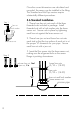
incorrect
correct
process pipe
brass sensor nut
bleed valve
make sure
bleed valve
clears isolation
valve handle