User’s Guide Shop online at www.omega.com e-mail: info@omega.
OMEGAnet® Online Service www.omega.com Internet e-mail info@omega.com Servicing North America: USA: One Omega Drive, P.O. Box 4047 Stamford CT 06907-0047 TEL: (203) 359-1660 e-mail: info@omega.com ISO 9001 Certified Canada: 976 Bergar Laval (Quebec) H7L 5A1 TEL: (514) 856-6928 e-mail: info@omega.
Chapter Page 1 Introduction 1.1 Description 1.2 Theory of Operation 1 1 1 2 2.1 2.2 2.3 Installation and Wiring Location of Fitting Sensor Position Sensor Wiring 2 2 2 3 3 3.1 3.2 3.3 3.4 3.5 3.6 3.7 Installation Hardware, Standard Sensor Hardware, Hot-Tap Sensor Standard Fitting Installation Hot-Tap Fitting Installation Calculating the H Dimension Standard Installation Hot-Tap Installation 4 4 4 4 5 6 8 10 4 Sensor Removal Procedures 4.1 Standard Sensor Removal 4.
.
Important Safety Information! CAUTION: (Standard version) Never remove the flow sensor from a pressurized pipe. Always wear safety face protection during sensor installation/removal. (Hot-Tap version) Follow the recommended installation/removal instructions in this manual. Always wear safety face protection during sensor installation/removal. Pipe fittings MUST be installed by a certified welder only. OMEGA will not assume liability of any kind for improper fitting installations.
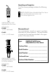
Unpacking and Inspection Your flow sensor package includes the following items: OMEGA FP-6000 Series Adjustable Brass Flow Sensor 6 inch ruler (Standard sensor version only) 10 inch brass alignment rod OMEGA FP-6000, -6001 Adjustable Brass Flow Sensor Order Number: FP-6000 1-1/2 in. NPT threads FP-6001 7/1-R 1-1/2 ISO threads Warranty Record For your protection, record your sensor's purchase information for future reference.
This manual contains description, specifications and instruction for the installation, removal, and operation of the OMEGA FP-6000 Series Adjustable Brass Flow Sensor. Please read the manual thoroughly. If you require further assistance, please contact your OMEGA dealer. Chapter 1 Introduction 1.1 Description The FP-6000 Series is an insertion flow sensor used to measure the flow velocity of fluids through process pipes.
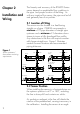
Chapter 2 The linearity and accuracy of the FP-6000 Series sensor depend on predictable flow conditions in the pipe and proper location of the fitting. As with any insertion flow sensor, the pipe must be full and generally free of air pockets. Installation and Wiring 2.1 Location of Fitting The sensor must be located in a free-flowing straight run of pipe.
(max. 30°) will help to avoid these problem areas, but use caution. Excessive angles will cause bearing drag at lower flow rates. On a vertical pipe run locate the sensor where the flow is upward. If downward flow is necessary the system must be designed to prevent air/water vapor pockets from developing in the pipe which will affect the performance of the sensor. 0° -30° Figure 2 Sensor Installation Range +30° Vertical mounting is recommended to provide best overall performance.
Chapter 3 Installation The following items are required to properly install the OMEGA FP-6000 Series Adjustable Brass flow sensor. 3.1 Hardware, Standard Sensor • female pipe fitting (weld-on or saddle) 11/2 in. NPT or ISO 7/1-Rc 1-1/2 • 11/4 in. (32 mm) diameter drill • Pipe thread sealant • Tape measure 3.2 Hardware, Hot-Tap Sensor The Hot-Tap sensor requires all the above items plus: • Hot-Tap drilling machine (e.g.
4. Remove brass sensor nut from sensor. brass sensor nut process pipe pipe fitting (Teflon tape recommended) 5. Thread brass sensor nut into pipe fitting. 3.4 Hot-Tap Fitting Installation 1. Install the pipe fitting on the outside diameter of the pipe according to the manufacturer's instructions. Failure to follow these instructions may result in bodily injury and/or product failure. 2.
brass sensor nut bleed valve make sure bleed valve clears isolation valve handle process pipe 4. Open the isolation valve and insert the drill through the valve and cut the sensor clearance hole. After the hole is cut, withdraw the drill from the isolation valve and close the valve. Remove the drilling machine per manufacturer's instructions. 5. Install brass sensor nut/bleed valve into the top of the isolation valve. Make sure the bleed valve clears the handle of the isolation valve during operation.
Standard Sensor H = 5.95 - pipe wall thickness - (0.10 X I.D.) Record your pipes "H" dimension for future reference: Example: 3.0 inch schedule 80 wrought steel; Wall thickness= 0.3 in. Inside diameter = 2.9 in. H= _________________ H = 5.95 - 0.3 - (0.10 X 2.9) H = 5.36 in. sensor flange alignment rod "H" process pipe pipe side view direction of flow Hot-Tap Sensor H = 15.00 - pipe wall thickness - (0.10 X I.D.) Example: 10 inch schedule 40 wrought steel; Wall thickness= 0.365 in.
Once the correct dimensions are calculated and recorded, the sensor can be installed in the fitting. The Standard and Hot-Tap versions require substantially different procedures. 3.6 Standard Installation Step 1 hex nut lock washer brass sensor nut Step 2 1. Thread one hex nut onto each of the three threaded rods included in package. Install threaded rod with a lock-washer onto the brass sensor nut. Secure rods in place by tightening each hex nut against the brass sensor nut. 2.
4. Place the alignment rod in the hole on the sensor flange. Align the flange so rod is parallel to the process pipe. sensor flange alignment rod direction of flow process pipe (top view) The flow sensor alignment rod MUST be parallel to the process pipe as shown. 5. Thread upper hex nuts with lock-washers until they contact the sensor flange and tighten. Check for proper "H" dimension and readjust if necessary. cap nuts sensor flange upper hex nuts and lock-washers FLOW lower hex nuts jam nuts 5.
3.7 Hot-Tap Installation Step 1 hex nut lock washer brass sensor nut Step 2 1. Thread one hex nut onto each of the three threaded rods included in package. Install threaded rod with a lock-washer onto the brass sensor nut. Secure rods in place by tightening each hex nut against the brass sensor nut. 2. Thread one jam nut and lower hex nut onto each stud so the top surface of each nut is 13.75 in. (350 mm) from top surface of brass sensor nut. Secure each hex nut with a jam nut.
3. Wipe the FP-6000 Series sensor body with a dry, clean cloth. Orient the alignment hole on the sensor flange to point downstream. Place the slotted flange over the threaded rods. Lower the sensor into fitting until the sensor flange rests on the lower hex and jam nuts. 4. Secure the sensor with lock-washers and upper hex nuts on the top of the flange. Before tightening, align the sensor flange so that the alignment rod is parallel and level with the process pipe. 5.
Using the Hot-Tap Installation Tool The Hot-Tap installation tool helps to lower the sensor into place against the pressure in the pipe. 1. Thread protector plate hex nuts onto each of the three threaded rods. Adjust each hex to a height of approximately 1 in. (25 mm) from the top of each rod. Remove the black plastic cable grommet in top of sensor with a screwdriver. Slide the grommet up the cable away from sensor. 2.
3. Align the sensor cable with the swivel mount cable port to prevent cable pinching. Use a 3/8 inch wrench or socket to turn the installation tool shaft clockwise until it is seated in the hole at the top of the sensor flange. 4. Wearing safety face protection, slowly open the isolation valve to the full open position. Loosen the lower hex and jam nuts and move them to the required "H" dimension. Turn the installation tool shaft clockwise until the sensor flange contacts the lower hex and jam nuts.
Chapter 4 4.1 Standard Sensor Removal To remove the Standard FP-6000 Series sensor from a depressurized empty pipe, simply remove the cap nuts and upper hex nuts located above the sensor flange. Pull up on sensor flange with twisting motion. Sensor Removal Procedures 4.2 Hot-Tap Sensor Removal To remove the Hot-Tap sensor safely from a pressurized active pipe, the entire installation process must be reversed. protector plate cap nuts protector plate protector plate hex nut 1.
installation tool threaded shaft cap nuts protector plate hex nuts sensor cable upper hex nuts installation tool bearing plate swivel mount w/cable port sensor flange 1 lower hex nut and jam nut sensor body 5. Wearing safety face protection, turn the installation tool shaft counterclockwise to withdraw sensor until the sensor flange contacts the upper hex nuts. 6. Raise one lower hex and jam nut to bottom of sensor flange. 7. Close valve, remove bearing plate and tool. To remove the sensor 8.
Chapter 5 5.1 Maintenance Maintenance and Replacement Parts 5.2 Replacement Parts All versions of the FP-6000 series sensor require little or no maintenance, with the exception of an occasional sensor/paddlewheel cleaning. (Standard version) 1. Standard sensor assembly FP-6000, -6001 2. Rotor kit (bearings, shaft, retainers, and rotor included), see table below♦ • FP52509-1 kit with stainless steel shaft • FP52509-2 kit with Tungsten Carbide shaft 3.
5.3 Rotor Replacement Procedure Rotor Pin 1. With a small pair of needle-nose pliers, firmly grip the center of the rotor pin (axle) and with a twisting motion, bend the rotor pin into an "S" shape. This should pull the ends of the pin out of the shaft retainers and free the rotor assembly. 2. Remove shaft retainer from each side by gently tapping it inwards using a punch. Install a new shaft retainer with the rotor shaft clearance hole inward. Only install one shaft retainer at this time.
H Dimensions H Dimensions for Standard Sensors Wrought Steel Pipe Per ANSI 36.10 NPS SCH 40 SCH 80 1-1/2 in. 2 in. 2-1/2 in. 3 in. 3-1/2 in. 4 in. 5 in. 6 in. 8 in. 10 in. 12 in. 14 in. 16 in. 18 in. 20 in. 22 in. 24 in.. 5.644 5.589 5.500 5.427 5.369 5.310 5.187 5.064 4.830 4.583 4.350 4.200 3.950 3.700 3.475 * 3.000 5.600 5.538 5.442 5.360 5.296 5.230 5.094 4.942 4.688 4.400 4.125 3.950 3.675 3.400 3.125 2.850 2.575 in. in. in. in. in. in. in. in. in. in. in. in. in. in. in. in. in. in. in. in.
H Dimensions H Dimensions for Hot-Tap Sensors Wrought Steel Pipe Per ANSI 36.10 NPS SCH 40 1-1/2 in. 2 in. 2-1/2 in. 3 in. 3-1/2 in. 4 in. 5 in. 6 in. 8 in. 10 in. 12 in. 14 in. 16 in. 18 in. 20 in. 22 in. 24 in. 14.694 14.639 14.550 14.477 14.419 14.360 14.237 14.144 13.880 13.633 13.400 13.250 13.000 12.750 12.525 * 12.050 SCH 80 in. in. in. in. in. in. in. in. in. in. in. in. in. in. in. in. 14.650 14.588 14.492 14.410 14.346 14.280 14.144 13.992 13.738 13.450 13.175 13.000 12.725 12.450 12.175 11.
K-factors Stainless Steel SCH 40S STAINLESS STEEL PIPE PER ANSI B36.19 K-FACTOR K-FACTOR A-FACTOR A-FACTOR SCH 5S STAINLESS STEEL PIPE PER ANSI B36.19 K-FACTOR K-FACTOR A-FACTOR A-FACTOR PIPE SIZE 1 1/2 2 2 1/2 3 3 1/2 4 5 6 8 10 12 14 16 18 20 22 24 PULSES/ U.S. GAL 104.200 67.160 46.060 29.790 22.060 16.890 10.6500 7.1160 3.8700 2.3570 1.6060 1.2980 0.9620 0.7400 0.5900 0.4790 0.3990 PULSES/ LITER 27.5297 17.7437 12.1691 7.8705 5.8283 4.4624 2.8137 1.8801 1.0225 0.6227 0.4243 0.3429 0.2542 0.1955 0.
K-factors Wrought Steel STD WROUGHT STEEL PIPE PER ANSI B36.10 K-FACTOR K-FACTOR A-FACTOR A-FACTOR PIPE SIZE 1 1/2 2 2 1/2 3 3 1/2 4 5 6 8 10 12 14 16 18 20 22 24 PULSES/ U.S. GAL 122.000 78.690 55.630 35.530 26.070 19.840 12.090 8.0410 4.3500 2.6080 1.7400 1.3950 1.0220 0.7800 0.6150 0.4970 0.4110 PULSES/ LITER 32.2325 20.7900 14.6975 9.3871 6.8877 5.2417 3.1942 2.1244 1.1493 0.6890 0.4597 0.3686 0.2700 0.2061 0.1625 0.1313 0.1086 U.S. GPM/HZ 0.4918 0.7625 1.0786 1.6887 2.3015 3.0242 4.9628 7.4618 13.
K-factors Plastic Pipe Schedule 80 Plastic pipe per ASTM-D-1785 K-FACTOR K-FACTOR A-FACTOR A-FACTOR Schedule 40 Plastic pipe per ASTM-D-1785 K-FACTOR K-FACTOR A-FACTOR A-FACTOR PIPE SIZE 1 1/2 2 2 1/2 3 3 1/2 4 5 6 8 10 12 22 PULSES/ U.S. GAL 124.400 80.140 56.730 36.180 26.500 20.140 12.250 8.1430 4.3980 2.6340 1.7770 PULSES/ LITER 32.8666 21.1731 14.9881 9.5588 7.0013 5.3210 3.2365 2.1514 1.1620 0.6959 0.4695 U.S. GPM/HZ 0.4823 0.7487 1.0576 1.6584 2.2642 2.9791 4.8980 7.3683 13.643 22.779 33.
General Data Flow velocity range: 1.6 to 20 ft/s 0.5 to 6 m/s Linearity: ±1% of full range Repeatability: ±0.5% of full range Pipe sizes: Standard version: Hot-Tap version: Cable length: Materials Sensor material: Specifications 1.5 to 24 in. (38 to 610 mm) 1.5 to 36 in. (38 to 914 mm) 25 ft (7.6 m), can extend up to 200 ft (61 m) without amplification C36000 free cutting brass Rotor material: CD4MCu stainless steel Rotor bearings: Fluoroloy B® Rotor shaft: 316 stainless steel (opt.
Specifications operating pressure: 225 psi (15 bar) Maximum operating temperature: 212°F (100 °C) Caution: The FP-6002 and FP-6003 Series HotTap system's overall specifications and limitations depend on the lowest maximum rating of the components associated with the system. For example, a ball valve, a component of the system, is rated at a maximum 100 psi @ 185°F, limiting the entire system's maximum pressure/temperature rating to 100 psi @ 185°F.
WARRANTY/DISCLAIMER OMEGA ENGINEERING, INC. warrants this unit to be free of defects in materials and workmanship for a period of 13 months from date of purchase. OMEGA’s WARRANTY adds an additional one (1) month grace period to the normal one (1) year product warranty to cover handling and shipping time. This ensures that OMEGA’s customers receive maximum coverage on each product. If the unit malfunctions, it must be returned to the factory for evaluation.
Where Do I Find Everything I Need for Process Measurement and Control? OMEGA…Of Course! Shop online at www.omega.