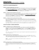
Programmable Dual Channel Monitor DP3300 Series User's Manual OMEGA ENGINEERING, INC.
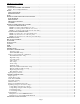
DP3300 Series User’s Manual SPECIFICATIONS:............................................................................................................................................................................3 DESCRIPTION:..................................................................................................................................................................................4 SAVING PROGRAMMED PARAMETER: ..........................................................................
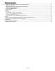
DP3300 Series User’s Manual Turning a Channel ON or OFF .....................................................................................................................................................18 MODES OF OPERATION FOR A PULSE INPUT CHANNEL:................................................................................................18 SETUP FOR COUNTER:..............................................................................................................................................
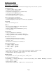
DP3300 Series User’s Manual SPECIFICATIONS: (Typical @ 25C and rated supply voltage unless otherwise specified) STANDARD INPUTS • * 4-20ma 10-50ma 0-5Vdc 0-10Vdc • Thermocouple inputs: J,K,T,E,R,S,B • Cold junction compensation error: +/- 1C (10C to 40C) • Open input indication: HELP displayed • Temperature displayable in Degrees C or F • Non standard inputs available --- consult factory.
DP3300 Series User’s Manual DESCRIPTION: A highly versatile series, DP3300 offers a unique combination of two analog channels or two pulse input channels or a combination of pulse (square wave) on one channel and an analog signal on the other. This feature allows it to be used as counter, rate, RPM or a frequency monitor along with displaying an analog signal such as 4-20ma loop current, voltage or millivolts or a temperature signal from thermocouples, RTDS etc.
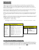
DP3300 Series User’s Manual Table 1. How to Display Parameters TO DISPLAY PERFORM FOLLOWING STEPS 1) Channel 1’s Process value a) Push CH SEL key once. 2) Channel 2's Process Value a) Push CH SEL key twice. First push selects channel 1 and the second push will select and display channel 2's process reading.
DP3300 Series User’s Manual RESETTING PEAKS Peaks can be reset to current process value e.g. if channel 1 is reading 200 C, its peaks can be reset to 200. This will allow tracking from the current process reading. To reset high peak, first select the channel whose peak is desired to be reset (by pushing the ‘CH. SEL’ key). Once the channel has been selected, push the ‘HI/LO’ key and keep it pushed. The display will read 'CHx HI' (x=channel #) following which the value of high peak will be displayed.
DP3300 Series User’s Manual below the limit (minus the relay) deadband. The second mode is manual reset. Once the limits are energized, they will stay energized until manually reset. (NOTE: In the RPM mode, the rate time base must be smaller than the selected filter value. If not, the system will automatically consider the filter value as the time base for rate calculation. Also, a difference of 0.500 is recommended between the filter and time base).
DP3300 Series User’s Manual MODES OF OPERATION FOR COUNTER: COUNT UP CONFIGURATION: MODE 0: (Count up with manual reset to zero) In this mode the system counts up from zero. Preset limits energize when the count reaches presets limit values. The unit will continue counting up until manually reset. To reset the count manually, first select a channel by pushing CH SEL key and ,while keeping CH SEL key pushed, simultaneously push the RESET key .
DP3300 Series User’s Manual RESETTING COUNT: The COUNT shown for each channel can be reset to zero or preset for a count down (depending on counter mode) at any time. To reset the count manually, first select a channel by pushing CH SEL key and ,while keeping the CH SEL key pushed, push the RESET key simultaneously. The display will read 'RESET' and then the reset value of zero will be displayed.
DP3300 Series User’s Manual the indication of the elapsed time. Maximum time indicated is 999.59.59 hours. To reset the timing and start it all over again, first push the TIME key and while keeping it pushed, press the RESET key. The time will reset and start over from 000.00.00 hours. SETUP: Setup mode provides a means to customize the monitor to suit a particular application. It allows programming such parameters as temperature units, limits, display mode, relay deadband, etc.
DP3300 Series User’s Manual ‘Channel ON/OFF’ Setup After displaying input type, the next step turns a channel ON or OFF. This determines whether a channel is scanned and displayed or not. If for any reason a channel is not being used, it should be turned OFF. This will prevent the unit from spending any time scanning it and also from displaying a 'HELP' message if there is no signal connected to its input.
DP3300 Series User’s Manual suppose a flow transducer outputs a 0.130Vdc to 5.000Vdc signal which corresponds to a flow rate of 0 to 40 gal./min. Then to make the 0.130Vdc correspond to a display of 0, set OFFSET =0.130. NOTE: If the input type is CURRENT, the Offset value is entered in milliamps. If the input type is VOLTAGE, the Offset value is entered in millivolts.
DP3300 Series User’s Manual When this parameter is set for "Normally Closed", the relay is closed when readings are below LIMIT, and opens when the channel reading exceeds its LIMIT value. The display will show 'LTx N.O.' (where ‘x’ is the channel number) for a Normally Open setting or 'LTx N.C.' for a 'Normally Closed' setting. Use ^v key to toggle between two settings. Once the desired setting is displayed, push SETUP key to go on to setting up limits 2 and 3 for the channel. The display format is 'LT2 N.
DP3300 Series User’s Manual Display Options On pushing SETUP key while the display is flashing SYS , the display briefly shows 'dSP OPt' (for display option) and then the current Display Option setting. Following display options are selectable. Use ^v key to step thru these options. Once the desired Display Option is shown, push SETUP key to enter the setting and go to set Display Time.
DP3300 Series User’s Manual 1. Connect a thermocouple calibration source to the unit. 2. Dial in 1100 degrees centigrade on the calibrator (Note: unit must be programmed for displaying in centigrade). 3. Adjust the gain pot (see diagram of rear view of instrument) on the back of the instrument until the display reads '1100'. 4. Short Channel #1's input with a wire or shorting bar (make sure to disconnect the calibrator so as not to damage it). 5. Push DATA key.
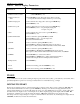
DP3300 Series User’s Manual FLOW CHART FOR ANALOG INPUT SET UP SYSTEM OR CHANNEL SYSTEM SETUP CHANNEL SETUP Select Channel Thermocouple / RTD / Thermister Setup Select Display Option 1.Scan 2.High point 3.Low point 4.CH 1 – CH 2 5.CH 2 – CH 1 6.
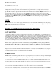
DP3300 Series User’s Manual FLOW CHART FOR PULSE INPUT: SET UP Select System or Channel Programming Turn CH On/Off For System Programing Refer to Flow Chart for Analog Input SELECT INPUT TYPE 1. Voltage 2. Current 3. J T/C 4. K T/C 5. T T/C 6. E T/C 7. Pulse Low Freq. High Freq. Rate RPM Counter Scaler Scaler Enter Rate Time Base Select Filter Value Division Factor Division Factor Select Counter Mode 0,1,2,3,4,5 Enter Limits (1 thru 3) Enter Limits (1 thru 3) Select Dec.
DP3300 Series User’s Manual SETUP FOR A PULSE CHANNEL: Turning a Channel ON or OFF The very first thing after selecting a channel is to turn it on or off. A channel should be turned off if it is not being used. Use ^v key to select the desired setting. If a channel is OFF, the display will show 'CHx OFF' (where ‘x’ is the channel number) and if it is ON the display is 'CHx ON'. Use ^v key to display the desired ON/OFF setting, and then push SETUP key to go to the next parameter.
DP3300 Series User’s Manual FUNCTION DISPLAY SHOWS TO CHANGE active digit flashing. active digit. Division Factor 'dIV FAC' followed by preset division factor e.g. 12 with active digit flashing. Push ^v key to increment or decrement active digit. Push key to change active digit. Limit 1 Limit 2 Limit 3 'CH1 LT1' followed by preset Limit 1 value e.g. 123.4 with active digit flashing. For limits 2 &3 CH1 LT2, CH1 LT3 followed by limit value. Push ^v key to increment or decrement active digit.
DP3300 Series User’s Manual FUNCTION DISPLAY SHOWS Latching or non latching relay setup. 'LATCH' for latching mode. 'NON LCH' for non latching mode. Limit outputs programmed as normally open or closed LT1 N.O. or LT1 N.C LT2 N.O. or LT2 N.C LT3 N.O. or LT2 N.C TO CHANGE Push ^v key to obtain alternate mode. Use ^V key to obtain alternate mode.
DP3300 Series User’s Manual If the unit is setup as an RPM monitor then following steps are performed for setting up various parameters: FUNCTION DISPLAY SHOWS Filter value 1,2,4,6,10,15,20,30,60 Push ^v key to obtain desired value Decimal point placement dP dP dP dP Push ^v key to move decimal point to desired position. 9999 999.9 99.99 9.999 TO CHANGE Scaler 'SCALER' followed by preset scaler value e.g. 10.00024 with active digit flashing. Push ^v key to increment or decrement active digit.
DP3300 Series User’s Manual NOTE: Process value for respective relay must be below limit value for it to reset. Other wise the key sequence will be ignored. Open Collector (solid state) output Option: DP3300 units can be ordered with either open collector outputs or electro-mechanical relays. (Check model number printed on the unit for option). If ordered with open collector outputs, then these outputs are programmed during Setup to operate as either Normally Open (NO) or Normally Closed (NC).
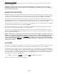
DP3300 Series User’s Manual FIG. 3: Power, Input/Output connections & rear view of the instrument.
DP3300 Series User’s Manual MOUNTING 3.70” (94mm) 0.15” dia. (3.81mm) 1.77” (45mm) 4.05” (102.87mm) Figure 4. Panel Cutout Dimensions 1. Cut out Panel and mounting hole dimensions as shown in figure 8 above. 2. Remove the nuts from the mounting screws on the Panel Meter (see picture below). 3. Insert panel meter into the hole until it is flush with the panel. Install the nuts and tighten them till the unit is held firmly against the panel. 1.
DP3300 Series User’s Manual WARRANTY/DISCLAIMER Page25
DP3300 Series User’s Manual Page26
DP3300 Series User’s Manual Page27