
Network Card User Manual

4. Register Description and Programming
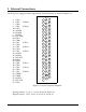
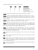
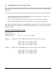
The DAQ-12 uses 16 consecutive I/O address locations in the range 0 to FFFFH. The card
utilizes these addresses for the registers listed in Table 4-1. (* indicates registers located in
8254 counter).
Read/Write 8-bit 8254 Control Word/Status Register
Base F *
Read/Write 8-bit Multi-function Timer Register
Base E *
Read/Write 8-bit Clock Rate Register (high)
Base + D *
Read/Write 8-bit Clock Rate Register (low)
Base + C *
Reserved
Base A, B
Read/Write 8-bit Gain Control Register
Base 9
Read/Write 8-bit Digital Input/Output Register
Base + 8
Write only 16-bit D/A Channel 1 Register
Base + 6, 7
Write only 16-bit D/A Channel 0 Register
Base + 4, 5
Write only 16-bit Start Conversion Register
Read only 16-bit A/D Data Register
Base + 2, 3
Read/Write 16-bit Control Word Register
Base + 0, 1
Table 4-1. DAQ-12 Address Map
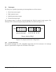
4.1 Register Description
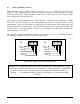
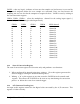
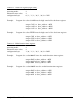
4.1.1 Control Word Register
The control word register defines and controls many of the DAQ-12'S data conversion
functions. This register is 16-bit read/write.
Write Read Write Read
D15 INT2 INT2 D7 RUN RUN
D14 INT1 INT1 D6 0 EOC
D13 INT0 INT0 D5 0 VALID
D12 DMAEN DMAEN D4 DMASL DMASL
D11 DMACT DMACH D3 CHSL3 CHSL3
D10 LEVEL LEVEL D2 CHSL2 CHSL2
D9 TRIG TRIG D1 CHSL1 CHSL1
D8 CLK CLK D0 CHSL0 CHSL0
DAQ-12 Users Manual 25