
Stud Sensor User Manual

its
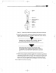
“cross-flow” holes with
the exiting process flow path as shown in Figure
2-3.
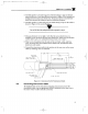
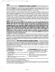
After tightening the compression nut, the ferrule will be
permanently crimped. Therefore, make sure that the sensor is
inserted to the proper depth before tightening the compression
nut.
C. With the
sensor properly positioned, tighten the compression nut onto the
compression fitting to crimp the ferrule. Use one wrench to hold the fitting
and another to turn the nut 1 to 1% turns. This should provide an effective
process seal. Also, the crimped ferrule becomes a convenient reference
indicator for insertion depth when re-inserting the sensor after cleaning.
This completes the insertion mounting
or
direitly in the process
flow path.
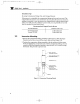
Rotate the sensor to align one
and
oosition the sensor’s “cross-flow” holes at the center of the tee,de&h to
PROLESS
FLOW
Figure
2-3.
Compression Fitting Parts Arrangement For Insertion Mounting
B.
Insert the sensor into the compression fitting. Then adjust the insertion
;pC$;;ESSION
REDUCER
(AS
REQUIRED)
;tYoN
TWO-PIECE FERRULE
(ORIENT IN THIS DIRECTION)
lnsta~~ation
OPTIONAL
-
f
CDE681 Part 2
,
-
m
2:14
PM Page 5
7/17/03
M3594m0603mCDE681Series.qxd