Shop online at (omega.com@j wwbv.omega.cum e-mail: info@omega. cor n STAMFORO.CT MAKCHESlEfl.
M3594-0603-CDE681Series.qxd l/11/03 2:14 PM Page cov4 h omega .com@ m * EGA OM ! Y-f Internet e-mail info@omega.com OMEGAnet@ Online Service www.omega.com Servicing North America: USA : IS0 9001 Certified Canada: One Omega Drive, P.O. Box 4047 Stamford CT 06907-0047 TEL: (203) 359-1660 e-mail: info@omega.com FAX: (203) 359-7700 976 Bergar H7L 5A1, Canada Lava1 (Quebec) TEL: (514) 856-6928 e-mail: info@omega.
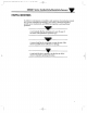
M3594-060%CDE681Ser -ies.qxd 7/17/03 2:14 PM Page i m CDE68 1 Series Conductivity/Resistivity Sensors .- HELPFUL IDENTIFIERS In addition to information on installation and operation, this instruction manual may contain WARNINGS pertaining to user safety, CAUTIONS regarding possible sensor malfunction, and NOTES on important, useful operating guidelines. A warning looks like this. Its purpose is to warn the user of this sensor of the potential for personal injury. A caution looks like this.
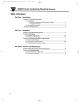
M3594-0603-CDEhElSeries.qxd 7/17/03 2:14 PM Page ii I_ m Table of Contents Part One - Introduction Section 1 General Information 1.1 Description: ....... .......................... Benefits of Enhanced Performance Design ......... ................................................................. Compatible Meters ..... ..................................................................... 1.2 Operating Precautions ..................................................................................
M3594-0603-CDE681Series.qxd 7/17/03 2:14 PM Page iii m CDE68 1 Series Conductivity/Resistivity Sensors List of Figures Figure 2-l General Dimensions and Cable Wire Details ............................................................ Figure 2-2 Insertion Mounting Details Fi ure 2-3 Corn % or Insertion Figure 2-4 .............................. ression Fitting Parts Arrangement R ounting . . . . . . . . . . . . . . . . . . . . . . . . . . . . . . . . . . . . . . . . . . . . . . . . . . . . . . . . . .
M3594-0603-CDE681Series.qxd 7/17/03 2:14 PM Pageiv f-t-? CDE68 1 Series Conductivity/Resistivity Sensors ’ I ‘ .
M3594-0603-CDE681Series.qxd 7/17/03 2:14 PM Page 1 m CDE681 Part 1 - Introduction w PART ONE - INTRODUCTION SECTION 1 - GENERAL INFORMATION Description 1.1 Benefits of Enhanced Performance Design CDE681-series compression fitting style sensors are manufactured to exacting tolerances using high quality, rugged materials for demanding ultrapure water and pure water applications.
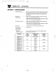
M3594-0603mCDE681Series.qxd 7/17/03 2:14 PM Page 2 I_ m - CDE681 Part 1 - Introduction SECTION 2 - SPECIFICATIONS Wetted Materials. Maximum Temperature ..... . Titanium electrodes (316 stainless steel outer electrode for extended sensor body style used with ball valve assembly), PTFE Teflon insulator, and treated Viton O-ring seals ........... .When used with Kynar (PVDF) compression fitting: 150°C at 1.7 bar (302°F at 25 psi) When used with 316 stainless steel compression fitting: 150°C at 13.
M3594m0603mCDE681Series.qxd 7/17/03 2:14 PM Page 3 m CDE681 Part 2 - lnstallatio PART TWO - INSTALLATION SECTION 1 - LOCATION REQUIREMENTS Locate the sensor as close as possible to the measuring instrument. Do not exceed a distance of 91 m (300 feet) between the sensor and instrument. SECTION 2 - Mounting The CDE681-series compression fitting style sensor may be insertion mounted into a pipe tee or vessel fitting.
M3594-0603-CDE681Series.qxd 7/17/03 2:14 PM Page 4 m - CDE681 Part 2 - Installation 1. Install a pipe tee of appropriate size (‘x to 2 inch) and material into the process pipe. If necessary, screw a respectively-sized reducer into the pipe tee. avoid leaks. Recommendation: Use Teflon tape or pipe sealant with Teflon. (Exception: For higher temperature solutions, sealing with Teflon tape may not be adequate.) SENSOR 6.
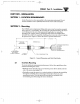
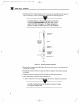
M3594m0603mCDE681Series.qxd 7/17/03 2:14 PM Page 5 m CDE681 Part 2 - lnsta~~ation OP T I ON AL N Yo ;t T WO P I ECE FERRU LE ( OR I EN TI N TH I S I REC D T I ON ) ; pC$ ;; ESS I ON REDUCER ( AS REQUIRED) PRO LESS FL OW Figure 2-3. Compression Fitting Parts Arrangement For Insertion Mounting B. Insert the sensor into the compression fitting. Then adjust the insertion , f de&h to oosition the sensor ’s “cross-flow” holes at the center of the tee, and direitly in the process flow path.
M3594-0603-CDE681Series.qxd 7/17/03 2:14 PM Page 6 I_ m CDE681 Part 2 - Installation Installation Tip! Re-using Compression Fitting, Nut, and Crimped Ferrule: If the sensor is re-installed, the compression fitting and nut can be re-used. The crimped ferrule, however, may need to be cut away from the sensor to remove it, making it unusable.
M3594-0603-CDE681Series.qxd l/17/03 2:14 PM Page 7 m 3. Route the sensor cable through a pipe of an appropriate material and length. Screw the compression fitting onto the end of the pipe (or coupling, if used). Recommendation: Use Teflon tape or (Exception: For higher temperature Teflon tape may not be adequate.) ipe sealant with Teflon. so Putions, sealing with 4. Fasten a Unilet junction box onto the other end of the pipe. 5. Run interconnect cable from the analyzer into the Unilet junction box.
M3594m0603mCDE681Series.qxd 7/17/03 2:14 PM Page 8 I_ m CDL681 Part 2 - Installation SECTION 3 - SENSOR/INTERCONNECT CABLE DETAILS 3.1 Sensor Cable Details The sensor’s integral cable is a 6-wire crosslinked polyethylene-jacketed cable with 4 conductors and two isolated shield wires. Refer to Figure 2-l for the function and color of each wire in the sensor ’s integral cable. 3.
M3594m0603mCDE681Series.qxd 7/17/03 2:14 PM Page 9 m CDE68 1 Part 2 - Installation 5. Carefully position a 2% inch long piece of shrink tubing or tape on the bare sensor shield wire %-inch from the end as shown in Figure 2-6 to insulate and distinguish it from the inner shield wire. Doing this exposes X-inch of bare shield wire beyond the tubing or tape for connection purposes. 6. Carefully position a l-inch long piece of shrink tubing or tape on the cable as shown in Figure 2-6 to secure all wires.
M3594&0603-CDE681Series.qxd 7/17/03 2:14 PM Page10 I_ m CDE681 Part 3 - Service and Maintenance PART THREE - SERVICE AND MAINTENANCE SECTION 1 - RECOMMENDED CLEANING PROCEDURE Keep the sensor reasonably clean to maintain measurement accuracy. The time between cleanings (days, weeks, etc.) is affected by the characteristics of the process solution and can only be determined by operating experience. 1.
M3S94m0603-CDE681Series.qxd 2.1 7/17/03 2:14 PM Page11 I_ m Checking Sensor Operation Use the troubleshooting section in the analyzer instruction manual to determine whether the sensor or analyzer is in-operative. If you suspect the sensor, check it using this procedure: 1. Disconnect the sensor from the analyzer (or junction box, if using interconnect cable). 2. Clean the sensor using the procedure in Part Three, Section 1. 3.
M3594-0603-CDE681Series.qxd 7/17/03 2:14 PM Page 12 I_ m CDE681 Part 3 - Service and Maintenance 2.2 Customer Assistance If you need assistance in troubleshooting or repair service, please contact your local OMEGA representative, or the OMEGA Customer Service Department at: l-800-633-2378 or l-203-359-1660. We can also be reached on the Internet at email: info at omega.com www.omega.com All sensors returned for repair or replacement must be freight prepaid and include the following information: 1.
M3594-0603-CDE681Series.qxd 7/17/03 2~14 PM Page cov5 (f, - I_ . . . . . . . . . %. . M ICLA ISWARRANTY/D ER : ~r~~~~~~~~~~~~~ :~~ ~~~~~~~~~~~~~~~ . F , Fq , % \ f OMEGA ENGINEERING, INC. warrants this unit to be free of defects i n m a t e r i a l s and w o r k m an sh i p f o ra o m da t e fo pu r chase . OM EGA’ sW ARRAN TY add s an iti ona ad lo pe r i od fmonths 13 o fr one r (1) year o cove rhand li ng and sh i pp i ng ti m e .
M3594-0603-CDE681Series.qxd l/17/03 2:14 PM Page cov2 h - Where Do IFind Everything INeed for Process Measurement and Control? OMEGA...Of Course! Shop online at www,omega.