
User manual


OLIMEX© 2012 SHIELD-EKG-EMG
SECTION 5 HARDWARE
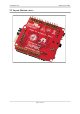
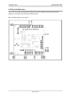
You can get a good view of the hardware observing the board. All pins, connectors and
jumpers are named individually.
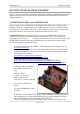
5.1 Arduino shield connector
These connectors follow the ARDUINO specification for shield connection. The shield comes
with soldered connectors making it ready for mounting on compatible board with the
possibility to have another shield mounted on it.
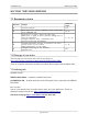
Pin # POWER CON1 ANALOG CON2 DIGITAL CON3 DIGITAL CON4
1 RST A0 D0 D8
2 3.3V A1 D1 D9
3 5V A2 D2 D10
4 GND A3 D3 D11
5 GND A4 D4 D12
6 Vin A5 D5 D13
7 - - D6 GND
8 - - D7 AREF
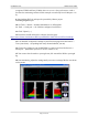
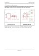
6-pin and 8-pin connectors mounted (CON1, CON2 and CON3, CON4):
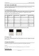
5.2 Trimmer TR1
Trimmer TR1 is calibrated during the factory testing. However it may be adjusted for the gain.
Use at own risk.
5.3 Jumper description
The names of the jumpers on the board correspond to the bold names used below:
3.3V/5V
This jumper controls the power circuit. Whether powered by 3.3V or 5V board.
Default state is 3.3V.
Page 14 of 20