
User manual
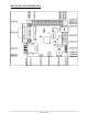

JUMPER DESCRIPTION
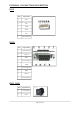
3.3V_E
When this jumper is closed, it enables 3.3V board power supply.
Default state is closed.
SCL_E
When this jumper is closed, it connects UEXT pin 5 (SCL) to UEXT pin 9 (SCK),
respectively PIC18F67J60 pin 2 (RE0/P2D) to PIC18F67J60 pin 34 (RC3/SCK1/SCL1).
Default state is opened.
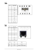
SDA_E
When this jumper is closed, it connects UEXT pin 6 (SDA) to UEXT pin 7 (SDI),
respectively PIC18F67J60 pin 1 (RE1/P2C) to PIC18F67J60 pin 35 (RC4/SDI1/SDA1).
Default state is opened.
When jumpers SDA_E and SCL_E are opened, UEXT pin 5 (SCL) is connected only to
PIC18F67J60 pin 2 (RE0/P2D) and UEXT pin 6 (SDA) is connected only to IC18F67J60
pin 1 (RE1/P2C), so you have to use software I
2
C. If you want to use hardware
software, you have to close (short) jumpers SDA_E and SCL_E, but note that this will
short PIC18F67J60 pin 2 (RE0/P2D) to PIC18F67J60 pin 34 (RC3/SCK1/SCL1) and
PIC18F67J60 pin 1 (RE1/P2C) to PIC18F67J60 pin 35 (RC4/SDI1/SDA1).
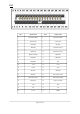
INPUT/OUTPUT
One user button BUT – connected to PIC18F67J60 pin 3 (RB0/INT0/FLT0).
Reset button RST – connected to PIC18F67J60 pin 7 (#MKLR).
Status red LED connected to PIC18F67J60 pin 44 (RB4/KBI0).
Power supply red LED PWR – indicates that external power source is applied and
board power supply is applied.
One trimmer AN_TR is connected to PIC18F67J60 pin 15 (RF3/AN8).
Page 11 of 36