Olimex PIC-KIT3 In-circuit programmer/debugger USER’S MANUAL Revision B, October 2013 All boards produced by Olimex LTD are ROHS compliant
OLIMEX© 2013 PIC-KIT3 user's manual DISCLAIMER © 2013 Olimex Ltd. Olimex®, logo and combinations thereof, are registered trademarks of Olimex Ltd. Other product names may be trademarks of others and the rights belong to their respective owners. The information in this document is provided in connection with Olimex products. No license, express or implied or otherwise, to any intellectual property right is granted by this document or in connection with the sale of Olimex products.
OLIMEX© 2013 PIC-KIT3 user's manual Table of Contents DISCLAIMER............................................................................................................. 2 CHAPTER 1: OVERVIEW........................................................................................4 1. Introduction to the chapter.................................................................................4 1.1 Features....................................................................................................
OLIMEX© 2013 PIC-KIT3 user's manual CHAPTER 1: OVERVIEW 1. Introduction to the chapter Thank you for choosing the PIC-KIT3 programmer/debugger manufactured by Olimex LTD.The first chapter focuses on the overview of the product. 1.1 Features • • • • • • • • • • • • USB (Full-Speed 2 Mbits/s) interface to host PC Real-time background debugging Supported in MPLAB X and MPLAB 8 Built-in over-voltage/short circuit monitor Firmware upgradeable from PC Supports low voltage down to 2.0 volts. (2.0 to 6.
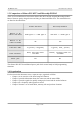
OLIMEX© 2013 PIC-KIT3 user's manual 1.3 Comparison of Olimex PIC-KIT3 and Microchip PICKit3 There are several differences between the Olimex PIC-KIT3 and the original Microchip PICKit3. Most of them are purely design choices and bring no functional differences.
OLIMEX© 2013 PIC-KIT3 user's manual CHAPTER 2: DEVICE DESCRIPTION 2. Introduction to the chapter This chapter features explanation of the interfaces visible to the user. Most of the time those would be the only parts of the PIC-KIT3 that the user manipulates or contact with. 2.1 Ports and connectors The user can freely access the USB and the ICSP connectors available. There is also a power jack near the USB. The pinouts and the usage of those are discussed below. 2.1.
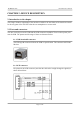
OLIMEX© 2013 PIC-KIT3 user's manual 2.1.3 Power jack The Olimex PIC-KIT3 has additional power jack which comes handy in field programming situations where you lack mini USB cable, but you have access to external power. The power jack should receive between (6-12)VDC and it is practical to already have an image uploaded in the PIC-KIT3 before using the power jack. The inner pin is the VDC, the outer plate is the GND. 2.
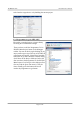
OLIMEX© 2013 PIC-KIT3 user's manual such from the target device or by building the current project. 2.3.2 Programmer-to-go in MPLAB X First make a standard project or import binary file using the recommended settings. Then you have to add the 'Programmer To Go PICKit3 Main Project' button to the debugger toolbar. You can do this by right-clicking on any empty toolbar space (up at the top of the IDE). A popup menu will appear. Choose the Customize menu item to get the Customize Toolbars dialog.
OLIMEX© 2013 PIC-KIT3 user's manual CHAPTER 3: SETTING UP PIC-KIT3 3. Introduction to the chapter More details about the standard connection routine of Olimex PIC-KIT3 and your target via MPLAB 8 and MPLAB X. 3.1 Hardware setup The required hardware for successful connection might vary depending on the target board and chip. PIC-KIT3 has a 6-pin male DIP header with 2.54mm (0.01'') pitch. 1) The first thing to consider is the target's connector's type. Some of the older boards have RJ11 connector.
OLIMEX© 2013 PIC-KIT3 user's manual (optional) 4. If asked for firmware update - allow it to download and do not disconnect while the device is updating (optional) 5. If you wish (and it is possible) you can power your target board/MCU via the PICKIT3 from Programmer Settings Power Choose desired voltage and check the box. 6.
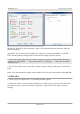
OLIMEX© 2013 PIC-KIT3 user's manual 3. Click Next → adjust destination folders and names 4. Click Next → review the information and choose to Finish (optional) 5. After the project is ready you adjust options by selecting and right-clicking over the project name and going to the “Properties” option. Mark the PICKit3 entry and take a look at the different drop-down options. You can set the power to the target board from there also.
OLIMEX© 2013 PIC-KIT3 user's manual CHAPTER 4: FREQUENTLY ASKED QUESTIONS Q: What USB cable do I need? A: You should have a USB type A-B cable to connect to PC, all PC USB hosts have USB-A connector while PIC-KIT3 has USB-B connector so the cable should be USB A-to-B type. Note that such a cable is not included in the package. Q: Does your ICSP connector layout differ from the ICSP connector layout of the original PICKIT3? A: Yes. This can be easily adjusted by proper mirrored cable.
OLIMEX© 2013 PIC-KIT3 user's manual CHAPTER 5: REVISION HISTORY AND SUPPORT 5. Introduction to the chapter In this chapter you will find the current and the previous version of the document you are reading. Also the web-page for your device is listed. Be sure to check it after a purchase for the latest available updates and examples. 5.1 Document revision Revision Changes Modified Page# A, 28.01.13 Initial release All B, 29.10.13 Swapped wrong picture about the ICSP connector.
OLIMEX© 2013 PIC-KIT3 user's manual 5.3 Product support For product support, hardware information and error reports mail to: support@olimex.com. Note that we are primarily a hardware company and our software support is limited. Please consider reading the paragraph below about the warranty of Olimex products. Warranty and returns: Our boards have lifetime warranty against manufacturing defects and components.