
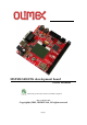
User manual
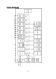

JUMPER DESCRIPTION
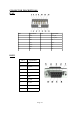
Power In jumper:
P_IN jumper connects power supply from JTAG connector. You have to
ensure that your circuit doesn't draw more than few milliampers current or the
power supply may decrease due to the JTAG port current limitations. P_IN is
useful and must be used mostly to program the microcontroller.
Power Out jumper:
P_OUT jumper connects power from MSP430-5438STK to JTAG connector.
When this jumper cap is placed, the power supply of JTAG connector will follow
the power supply of the board. This is useful when your board works at lower than
+3,3V power supply.
Note:
P_IN and P_OUT jumper caps should not be placed at the same time.
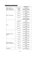
VDD_E
Enable MSP430F5438 3.3 V power supply.
Default state is closed.
3.3V_E
Enable 3.3V board power supply.
Default state is closed.
3.3VA_E
Enable 3.3V board analog power supply.
Default state is closed.
AGND_E
Enable board analog ground.
Default state is closed.
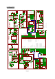
Input/Output
User joystick with name J1 – this is 4 directions plus center button, in the schematic
the joystick four directions switches are connected: UP, DOWN, LEFT, RIGHT -
through 33k resistors and CENTER through serial connected 330 and 33k resistors
to 3.3V.
Status LED (green) with name LED1 connected to MSP430F5438 pin 83 (P10.7).
Status LED (yellow) with name LED2 connected to MSP430F5438 pin 82 (P10.6).
Power supply LED (red) with name PWR – indicates that external power source is
applied and board power supply is applied.
Reset button with name RESET, connected to MSP430F5438 pin 96.
LCD black/white 84x48 pixels
Page 9