
User manual


OLIMEX© 2015 AVR-ISP-MK2 user's manual
cutting between the pads of the original position and soldering the pads of the new position. After
the change the jumper should be in PGM position. This changes the direction of programming on
the 10-pin ICSP connector – instead of programming – it would get programmed.
3. Connect a compatible programmer (able to program AT90USB162, it can also be another AVR-
USP-MK2) to AVR-ISP-MK2's 10-pin ICSP connector on one side and to your computer on the
other.
4. Download and extract the archive with the drivers (CLICK FOR DOWNLOAD).
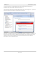
5. Launch your favorite programming tool (AVR Studio, Atmel Studio, AVRDUDE, etc.) and
import the elf – it is located in folder DEFAULT-ELF in the archive you downloaded in point 4.
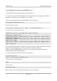
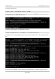
6. Program the AT90USB162.
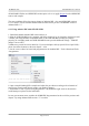
7. At this point you should test if the bootloader works as expected. It is now ready-to-use. Refer to
chapters 4.2 and 5.2 of this document for detailed institutions on how to use the bootloader to
connect to “Atmel Flip”. Note that to be able to use the ICSP interface for the programming of
targets you would need to perform the next step 8.
8. Switch back the position of the jumper to original position (after the switch the jumper should be
in position ER).
9. Test and carefully close the case.
5.4 Jumpers description
Please note that the two jumpers on the board are PTH (plated-through hole) type and should be
easy to mount/dismount.
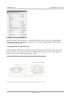
5.4.1 TARGET jumper
TARGET jumper controls the powering of the target board. If it is in position ON (check the
diagram on the back of the plastic cover) it will provide either 3.3V or 5V to the target board
(depending on the position of the POWER jumper)
The default position is OFF.
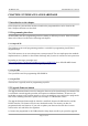
5.4.2 POWER jumper
If you have set the TARGET jumper to position ON POWER jumper controls whether 3.3V or 5V
are provided to the target board.
The maximum amperage available for both 3.3V and 5V modes is 300mA.
The default position is 5V.
Page 19 of 24