
Quickie 500 manual


Page 8 www.oldschoolmodels.com Construction Manual
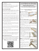
n Step 40 - Wing Assembly (tip sanding)
You will need to sand the tip to shape
at some point - either now, or once
the wing is completed. We chose to
get most of the rough sanding done
before joining the wings halves so
we could more closely compare the
shape of the port and starboard tips.
You should end up with a couple of
matching tips that look pretty close to
these photos.
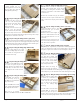
n Step 41 - Wing Assembly (R1 cutout and sanding.)
On the root rib (R1) you will now
need to cut out a square hole. This
will be between the pre-cut slots
for the sheer webs, as we've shown
here. Do this for both wing halves.
We carefully used a rotary tool to
do most of the work, then cleaned
up everything with a hobby knife.
Do not cut into the sheer webs as
you can weaken them.
Now take a little time and block
sand the root (R1) ribs to remove any
protruding sheeting and/or sticks. You'll need both of these ribs to
be sanded perfectly flat so they will properly butt-up against each
other in a couple steps.
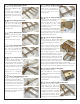
n Step 42 - Wing Assembly (D1, D2)
Locate D1 from LP1 and both
D2s from BP7.
These pieces are laminated
together with a thin layer
of epoxy to form the wing's
dihedral brace.
D1 will be sandwiched
between both D2s. To insure it
stays perfectly aligned, clamp
or weigh down this assembly
until the glue fully cures.
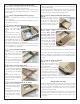
n Step 43 - Wing Assembly (join wing halves)
Now test fit the dihedral brace into the wing slots. You will
probably have to do a bit of sanding on the brace to allow it to
easily fit into each slot. Don't take off too much, too fast. Carefully
sand as necessary to make sure everything fits properly and the R1
ribs in each wing half are touching along their entire length when
assembled into a single wing. Take your time and get a good fit
that doesn't require a lot of force.
After test fitting, join the wing halves permanently with a bit more
30 minute epoxy. Remove the dihedral brace and apply the epoxy
into the pockets in each wing half and also coat the faces of each R1.
Slide all the dihedral brace into one of the wing halves, then slide
remaining wing half in place. Using a couple of clamps (or tape),
hold wing halves firmly together. Wipe off any excess epoxy and
remove the clamps only after the epoxy has fully cured.
Remember, any twist in the alignment of the panels cannot be
Before cutting
After cutting
fixed after the epoxy cures and will lead to a poor flying model.
If you choose to overpower and/or race this Q500, a thin
layer of fiberglass cloth (not included) should be added
around the perimeter of the center seam to add strength.
n Step 44 - Wing Assembly (cut holes for servo wires)
On the plans you'll see a callout suggesting a spot where a hole
needs to be cut in each side of the top WS sheeting. This hole
allows the aileron servo wires to pass through the sheeting and exit
the wing. Make these roughly 1/2" to 3/4" in diameter.
n Step 45 - Wing Assembly (optional strings)
This step is optional, but could make the aileron servo installation
a bit easier, once the wings are covered. Cut two 12” lengths of
string, one for the port wing, one for the starboard. Starting with
the port wing panel, push the thread through this hole just cut in
the previous step, then through the circular holes in R2, R3, and
R4. The string will now extend from the servo bay, out through the
bottom of the wing. Tape both ends of the string so they won’t
easily pull out. Do the same for the starboard panel.
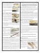
n Step 46 - Wing Assembly (wing dowels)
Remember those marks you
made on the leading edge of the
wing halves, showing where the
holes for wing dowels should be
cut? Well it's time to cut those
holes.
First, locate the 6” length of
1/4” dowel. Cut two 2-1/2” lengths and round one end of each
dowel, as shown in the photo.
Now cut the holes into the leading edge of the wing, making cure
they are centered on the leading edge strip. Cut the holes a bit
undersized, then gradually enlarge the holes into you get a nice,
snug fit. Test fit the dowels and note the feel as the dowel slips
through both internal WH4 pieces.
Place glue on the lower part of the dowel and insert the dowel
through both WH4s, leaving approximately 1/3” of the dowel
exposed.
This completes assembly of the Quickie 500 wing.
Now it’s time to start construction of the tail surfaces.
nPrepare your work area
Now tape a fresh piece of waxed paper on your building board.
nStep 47 - Horizontal Stab (ST1A, ST1B, ST2A, ST2B)
Locate ST1A from BP4, ST1B from BP5, ST2A from BP6 and ST2B
from BP3.
Each pair of these pieces
are glued together (A
to B) to form a stabilizer
sheet as you see here.
Make sure the pieces are
held perfectly flat while
the glue is curing.