
Quickie 500 manual


Page 14 www.oldschoolmodels.com Construction Manual
LG4. This relief will give the necessary clearance for the main gear
wire to fit into the slot. (Because this cut needs to be on an angle,
it's not something we can laser-cut for you ahead of time.)
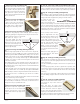
When these steps are
complete, slide both
main gear wires in place,
one forward of the other.
Now position a landing
gear strap on each side
as shown in this photo.
Using a 1/16” drill bit,
drill through the holes in
each strap, then use four of the included 2-56 x 3/4” self-tapping
screws to attach the straps to the fuselage.
Use the included 1/8” i.d. wheel collars to hold each wheel (not
included) on the axles. For a maintenance free installation, file
a small flat on the axle where the set screw of the wheel collar
touches. Also use a touch of thread-locking compound to keep the
screw from loosening over time.
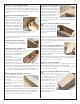
nStep 95 - Tail skid
Using the included wire, refer to the fuselage
plans as we give an example of how to bend
this wire into a simple tail skid.
The original Quickie 500 models used a skid instead of a tailwheel
to save weight and lessen wind
resistance.
When bent to the shape that
works for you, mark TW in the
two spots to be drilled, then drill
both holes to allow the skid to be
mounted as shown here.
nStep 96 - Covering
Now it’s time to cover your Quickie 500 airframe. Remove the main
gear, the tail skid and any of the control surfaces and hinges that
are still attached.
Double check that all surfaces are smooth and ready to cover. Sand
as necessary, then cover the rest of the airframe with the covering/
finish of your choice.
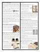
Logos, numbers, etc.
If you want to use graphics similar to the
ones we used, Old School Model Works
has teamed up with Callie Graphics as a
supplier for pre-cut vinyl. They are a very
well known provider of custom graphics
for R/C models.
We have supplied them with the artwork
needed to cut the any of our logos to the
sizes you need. You can order straight
from them, choosing the colors that work
for you.
Contact Callie Graphics at this link: https://callie-graphics.com or scan
this QR code.
Note that Callie Graphics is not affiliated with Old School Model
Works, nor does Old School Model Works generate any income
from this partnership.
The next steps shown are not in a particular order
but will all need to be done.
nAttach the Control Surfaces
Now is the time to attach the control surfaces to the airframe, by
gluing the hinges in position with a several smaller drops thin C/A
on each hinge.
nLanding Gear (main gear, straps, tail skid)
Re-attach the main gear wires and hold them in place with the
mounting straps and four 2-56 x 3/4” self-tapping screws. Also
hold the tail skid in place with a touch of glue, or mount your own
tailwheel assembly.
A note on the main gear. We've included 1/8" pre-bent gear that
works well. It is light-weight and will hold up for average flying. If
you fly off a rough field, or repeatedly perform hard landings, this
gear can bend. If this happens, it should be able to be bent back
by hand with a bit of pressure. Take care when landing to perform
nice, smooth landings where this won't be an issue. A hard landing
which dramatically bends the gear can reduce prop clearance
significantly.
nAttach wheels. Use the included 1/8” i.d. wheel collars to hold
each wheel (not included) on the axles (one for each wheel). For a
maintenance free installation, file a small flat on the axle where the
set screw of the wheel collar touches. Also use a touch of thread-
locking compound to keep the screw from loosening over time.
The following steps will show various pieces and parts which
are not included in your Quickie 500 kit. These are some of
the parts we referenced as “needed to purchase” towards
the front of this manual.
The parts shown in the photos were those we had on hand.
Please pay no attention to the brand names of these parts as
we aren’t recommending any particular brand.
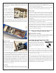
nRadio and pushrod installation
Shown here a few photos
of the pushrods and radio
gear installation in one of our
Quickie 500 prototypes. These
are shown only as a guide
because each installation is
unique and the radio system
you have might require
adjustments from what you
see here.
Make sure that when installing the control horns, they are placed
in-line with the pushrods, and that the line of holes where the
clevises attach are positioned over the hinge line.
For the average pilot, we recommend that clevises are attached to
the second outermost hole on each control horn.
We used mini-sized servos on our Quickie 500 prototypes and the
servo mounting holes cut into the servo tray are sized for them.
Other sizes of servos can be used but you might need to modify