
Quickie 500 manual


Construction Manual www.oldschoolmodels.com Page 11
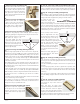
nStep 72 - Fuselage Assembly (H2, H3)
Locate both H2s and both H3s from LP2.
These form the hatch hold-down plates.
Glue one H2 to H3, then glue the other
H2 to H3 to form a left and a right piece.
Then glue these in place, into the top
notches of F3, and parallel with the fuse
sides as shown here.
nStep 73 - Fuselage Assembly (H4)
Locate H4 from LP2. It is glued
in place on the top of the firewall,
between the balsa strips as shown
here. Make sure it is flush with the
top edges of both fuselage sides.
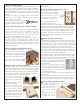
nStep 74 - Fuselage Assembly (wing alignment)
To align the wing properly on the fuselage, place the wing in
position, by pushing the wing dowels into the pre-cut holes in F3.
Lightly sand if necessary for a smooth fit.
Then allow the wing to rest
in the wing saddle. The wing
is perfectly aligned when the
distance from the left wing tip
to the rear of the fuselage is the
same the distance when measured
from the right wing tip.
nStep 75 - Fuselage Assembly (drill wing bolt holes)
With the wing aligned, drill two 3/16” holes for the wing bolts,
using the pre-cut holes in WB1 as a guide. Carefully push the bit
down through both WB1 and WB2 before drilling. Once the bit is
resting on the surface of the un-drilled WH1/WH2/WH3 assembly
in the fuselage, then carefully drill through the WH1/WH2/WH3
assembly. Use caution to make sure the wing does not move until
both holes are drilled.
When drilling, take your time and make sure the drill is held so the
bit is perpendicular with the wing’s sheeting. This will make it so
the wing bolt goes in at an angle, but the screw’s head will be flat
on the wing surface.
Remove the drill, remove the wing and clean up around the new
holes you drilled. Then run a 1/4x20 tap through the WH1/WH2/
WH3 assembly so that the wing bolts will thread into this block. If
you don't have access to a 1/4x20 tap, you can also use a 1/4x20
steel screw.
A few drops of thin CA will help strengthen and secure the threads
you’ve cut after they've been tapped.
If you prefer, you can also use 1/4x20 t-nuts instead of threading
into the wood (not included). To use these you will first have to
enlarge the holes you just drilled to 1/4".
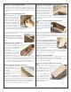
nStep 76 - Fuselage Assembly (stab support)
Using some scrap 5/16" square balsa,
cut two pieces to use as internal stab
supports as shown here. They should
both be flush with the top edges of the
fuselage.
n
Step 77 - Fuselage Assembly (round stab/fin leading edges)
Before installing the vertical fin and stab into the fuselage, take the
time to sand them and round off the leading edges of both pieces.
It’s much easier to do this now than to try it after they’re installed.
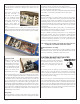
nStep 78 - Fuselage Assembly (stab alignment)
Although we’ve done everything possible to engineer the Quickie
500 so it will build straight and true, take a few minutes to guarantee
things indeed are straight before gluing on the tail surfaces.
To align the stab, first
install the wing. Now
place the horizontal stab
in place on the fuselage. Look at the fuselage straight on, from the
nose (or tail) and make sure that the stab is level with the wings.
If not, remove the stab and gently sand the stab support on the
high side, a little at time. Check the stab and re-sand the support if
needed until you see the stab as level.
Once leveled, ensure that the
stab is aligned with the wing
by measuring the distance from
the left wing tip to the left tip
of the stab. Compare this to the
distance between the right wing and
stab tip. Slide the stab a bit until these
two measurements are equal.
Make a couple of marks where
the stab touches the fuselage so
you can place it back in the same
position.
Remove the stab, apply glue on
the stab supports, then attach
the stab in place.
nStep 79 - Fuselage Assembly (vertical fin)
The vertical fin is installed next, with the fin’s tab sliding through
the slot pre-cut in the stab. Lightly sand the tab if necessary to get
a firm, slop-free fit.
Use the included large triangle to insure the fin is a perfect 90° to
the stab.
Once properly in position, it’s time to glue the fin in position. Take
a bit of time to make sure these glue joints are sufficient, but don’t
use too much glue as it will make the Quickie 500 unnecessarily
tail-heavy.
Also, don't put a large bead of glue between the fin and stab as
we'll be adding a support block to each side of the fuse in a later
step.
nStep 80 - Fuselage Assembly (LG4/LG5)
Locate LG4 and LG5 from BP1. These
are layered on top of each other as
shown here.
Note that there are small circles
engraved on both pieces. Make sure the
corners with these circles are aligned
(so the circles stack up). Whe properly
aligned, you should be able to see how
the offsets in LG4's slot will lineup with the pre-cut holes in LG5.
Keep the slot and holes clear of glue when assembling.
C C
BB
A A