
Quickie 500 manual


Page 10 www.oldschoolmodels.com Construction Manual
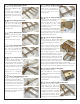
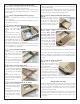
nStep 66 - Fuselage Assembly (BS)
Now the BS assembly is attached to the fuselage to form and align
the rear half.
First attach BS by pushing the large tab on the bottom of F5 into
the pre-cut slot on the front end of BS.
Then working one former at a time, carefully push the tabs in F6, F7
and F8 into the pre-cut notches in each fuselage side.
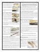
nStep 67 - Fuselage Assembly (TW1, TW2)
Locate TW1 and TW2 from LP1. These are
glued together, centering TW1 on top of
TW2, with their short, flat edges lined-up.
Then this assembly is glued to the back
of the fuselage as shown here.
nStep 68 - Fuselage Assembly (F1, F2)
Locate F1 and F2 from LP2. F2 is glued
in place on the front of the fuselage
as shown here. We recommend
using some epoxy for strength here.
Don't overdo it as we'll add more to
strengthen this area later on.
Use a bit more epoxy to glue F1 to
the front of F2. Clamp in place while
the glue cures.
nStep 69 - Fuselage Assembly (1/8" x 1/4" strips)
Locate two more of the 1/8"
x 1/4" balsa strips. These are
cut and glued to go along
the top edges of the fuselage
sides. They run from the front
of the stab mount at F8 all the
way up to the firewall (F2).
nStep 70 - Fuselage Assembly (WH3)
Locate eight WH3 from LP1 and
LP2. Two assemblies are made
by gluing stacks of four pieces
together as shown. Take care to
align the parts as you stack them.
nStep 71 - Fuselage Assembly (WH3)
Now the two WH3 assemblies from
the previous step are now glued
inside the fuselage, on top of the
each side of the WH1/WH2 piece
that was installed earlier.
the large WH2 tab will fit into F5 to aid in alignment and strength.
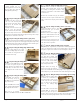
nStep 60 - Fuselage Assembly (F3)
Locate F3 from LP1. Glue this in place
as shown, making sure that the end
with the two holes is on the bottom of
the fuse (where the wing-saddle cut-
outs are).
nStep 61 - Fuselage Assembly (F3B)
Locate F3B from LP1. This is used
to double-up the wing holes in F3.
Glue this in place on the front of F3
(in the tank area), making sure that
the holes are perfectly lined up.
nStep 62 - Sanding (attach fuse sides)
Now the balsa sub-
assemblies are glued to each
side of the plywood fuselage
box. The sides are aligned by
the tabs that extend out of
the fuselage box.
We recommended gluing
one side at a time. Make sure
that each fuse side is held
flat on your work surface and properly glued to the sides of the
fuselage box (FS1).
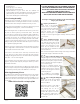
nStep 63 - Fuselage Assembly (F6, F7, F8)
Locate F6, F7 from BP1 and
F8 from BP2.
Each of these need to be
strengthened by adding a
strip of balsa to the top and
bottom as we show here.
Cut these pieces from the scrap 3/32" wood not used in BP9, BP10
and BP11. When gluing these scrap strips in place, make sure that
their grain runs cross-ways to the grain in the formers.
nStep 64 - Fuselage Assembly (1/8" x 1/4" strips)
Locate BS from BP1 and two
of the 1/8" x 1/4" balsa strips.
Measure, cut and glue these
strips so they are on top of
BS, along the outer edges and
matching the curvature of BS
as shown on the shaded areas
in this photo.
nStep 65 - Fuselage Assembly (BS)
Each of the F6, F7 and F8
formers are glued into place
as shown here, making sure
they are all 90° to the surface
of BS.
Glue them to BS as well as
the strips you just installed in
the previous step.
Balsa strips