
Fifty Six manual

Page 8 www.oldschoolmodels.com Construction Manual
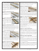
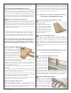
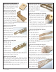
nStep 48 - Stab Assembly (ST)
Sand the both ends of the stab assembly so
there’s no extra trailing edge, leading edge
or stab material protruding past the S7 ribs.
Now locate 6 STs from BP10P and BP10S.
Make 2 tip assemblies by gluing 3 of them
on top of each other, aligned with each other.
Then lightly sand the long edge so it’s flat, then glue one assembly
to each tip of the stab, making sure you’ve properly aligned and
centered it on the S7 ribs.
nStep 49 - Elevator Assembly
Locate the two extra pieces of 5/16” x 1-1/4” tapered edge stock,
as well as one of the 6” lengths of 1/4” dowel. Cut the dowel to
length, as shown on the plans. Now measure and cut one elevator
half from each tapered edge balsa piece. Mark and cut the notches
into the leading edge of these elevator halves as shown on the
plans. Then glue each elevator half to the dowel, making sure the
entire piece is perfectly straight and flat.
This completes the assembly of the tail surfaces. Now it’s
time to assemble the fuselage. You won’t need to tape down
the fuselage plan to the board - simply use it as a reference.
However, you may need to put down some fresh waxed
paper as you’ll need it for a few of the steps.
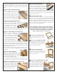
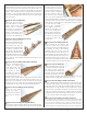
nStep 50 - Fuse Assembly (F3, F3A)
Locate F3 and F3A from LP2. Glue F3A to
F3 as shown here, making sure it is properly
aligned.
nStep 51 - Fuse Assembly (F4 and TR2)
Locate TR2 from LP2 and F4 from LP4.
Glue F4 into TR2 as shown here. Make sure
F4 is completely inserted into TR2 and is
held 90° to the surface of TR2.
nStep 52 - Fuse Assembly (F5)
Locate F5 from LP2. This is glued to the
back of TR2 as shown here, and pay close
attention to it’s orientation so you don’t
attach it up-side-down.
nStep 53 - Fuse Assembly (F3/F3A assembly)
Now attach the F3/F3A assembly
you created a few steps back, to
the front of TR2. Note that the F3
side should be attached to TR2, not
the F3A side. Again, make sure it’s
oriented correctly and is 90° to TR2.
the stab, then the other. Take the time to make sure everything
is aligned properly BEFORE you glue it in place, as it’s just about
impossible to fix if things are out of order and glued in place. When
finished, you should have something that looks just about like this
photo.
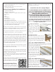
nStep 43 - Stab Assembly (trailing edge)
Locate one length of the 1/4” x 1/2”
balsa strip. Measure and cut this to
length to form the trailing edge of the
stab. Leave an extra 1/4” or so, then
glue this in place, using the pre-cut
“step” on the rear of each rib to help
hold it correctly in place. Make sure you
glue this piece to each of the stab’s ribs.
nStep 44 - Stab Assembly (leading edges)
Locate the other length of 1/4” x
1/2” balsa strip to use as the leading
edge of the stab. This will need to
be cut to length, and the root edges
beveled slightly to join correctly at
the stab’s center. Again, using the
“step” cut into the front of each rib, place these pieces in position
and glue them to each of the ribs, and to each other.
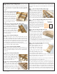
nStep 45 - Stab Assembly (center sheeting, top)
Using the un-cut sheet of 1/16th balsa,
it’s time to measure, cut and form
the center sheeting strips that will be
attached to each side of the vertical
fin. These sheets run from the top of
the S1 ribs (up against the vertical fin),
to cover the tops of the S2 ribs.
Using the same techniques that you
used when forming the wing’s center sheeting, measure and cut 3
total pieces to make each sheet. Take your time when measuring
and cutting - especially against the tapered edge of the leading
edge. What you want is a piece that fit snugly against the leading
and trailing edges as shown here.
Once you have made a pair of these, glue these in place on each
side over the S1 and S2 ribs, up against the vertical fin as we’ve
shown here.
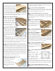
nStep 46 - Stab Assembly (VF3)
Remove the stab assembly from your
building board and flip it over. Remove all the
underside tabs by trimming them away, just
as you did on the wing. Make sure to continue
each of the rib’s aerodynamic shape.
Once that is finished, locate VF3 from BP11. This is glued in place
into the notch on the underside of the vertical fin. As shown here.
nStep 47 - Stab Assembly (center sheeting, bottom)
Using the same techniques as you
used on the top sheeting, measure,
cut and form the two strips of 1/16th
sheeting used on the bottom side.
When you are satisfied with their fit,
glue them in position as shown.