
Fifty Six manual

Construction Manual www.oldschoolmodels.com Page 3
• Pushrods (two 5” for ailerons, two 26” for elevator & rudder,
one 14” for nose gear steering, one 10” for throttle if glow.)
• Clevises for the pushrods.
• Wheels: one 2-1/4" for nose, two 2-1/2” for mains.
• Covering (2 rolls typically)
Additional Required Building Tools and Adhesives
• Drill & assorted drill bits
• Hobby knife and #10 blades
• Sandpaper: coarse (80 or 100 grit) & medium (150-200 grit)
• Pencil or pen
• Ruler
• T-Pins
• Waxed paper
• Building board
• 2-part epoxy (6 or 15 minute)
• Epoxy brushes and mixing sticks
•
Wood adhesives of your choice. We use medium viscosity CA
(cyanoacrylate) , but aliphatic resin and/or carpenter’s glues (used
correctly) will work just as well and give longer working time.
• Thin CA for attaching the included hinges
Although an easy to build kit, our Fifty Six kit is not for the novice
builder. We are assuming the builder is used to constructing balsa
kits and has the techniques and skills necessary to do so.
Closely inspect the supplied laser cut parts for damage. If you find
any damaged or missing parts, contact us immediately.
When removing the laser cut parts from their sheets, you’ll notice
the parts are held in place by several small “tabs”. These tabs
are uncut pieces of wood and can sometimes make it difficult to
remove a part. Rather than breaking and/or splintering the wood
by forcing out the part, we recommend removing any laser cut
parts from their sheets by using a hobby knife with a #10 blade.
A quick cut of the tab will allow the piece to be removed with no
damage. Sand any tab remainders flush with the part so there will
be no problem aligning them later.
It’s best to not remove parts from their sheets until they are needed.
Refer to Appendix A of this manual as a reference to what all the
laser cut parts look like and are called.
You’ll notice a check box next to each step. Check these off as
you go along so you don’t miss a step. Note that some steps (in
building the wing) have two boxes - this means that the step will be
done twice - once for each wing half.
There could be a step or two which leaves you a bit puzzled. If this
happens, step back and study the photo(s) for that step - both in
this manual and online.
All photos shown in this manual are of different Fifty Six prototypes.
Several pieces may have changed slightly
with improvements we’ve made so parts
may look a little different in some steps.
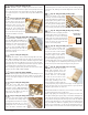
Online Supplementary Photos
We realize that the smaller black-and-
white photos in this manual might not
show some of the steps as clearly as you
might want. So we’ve anticipated this and made these photos
available on our website. You can either scan the QR code or type
this address into your browser:
www.oldschoolmodels.com/mpics/fiftysix/
IT IS VERY IMPORTANT THAT YOU ASSEMBLE THE FIFTY
SIX KIT IN THE ORDER DESCRIBED. SKIPPING FORWARD
IN THE STEPS COULD LEAVE YOU WITHOUT THE PROPER
LENGTHS OF WOOD TO FINISH THE KIT.
WE’VE INCLUDED ENOUGH WOOD TO EASILY COMPLETE
THIS KIT, BUT YOU MUST TAKE CARE TO PROPERLY
MEASURE AND NOT WASTE WOOD WHEN CUTTING.
Let’s begin construction by working on the port (left) wing
of your Fifty Six. Note that in these wing assembly photos,
there is an extra rib shown - that was eliminated in the final
prototype and production kits.
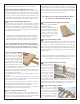
n Prepare your work area
You’ll need a flat building
surface that is a minimum of
36” long. Position the port
wing plan over the surface and
tape into position. Tear off a
length of waxed paper long
enough to cover the port wing plan and tape that into position,
over the plan.
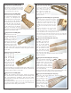
n Alignment triangles
Pre-cut into LP2 is a 90° triangle. This can
be used to vertically align any of the parts
in the construction of your Fifty Six. LP2 also
includes a foot piece that can be used with
the triangle to hold it vertically (hands-free).
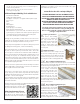
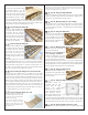
n n Step 1 - Wing Assembly (front spar)
These next few step will create the front spar. It is recommended
that you use a long, straight edge during these steps to ensure that
the finished spar is straight and true.
Locate one of the 1/4” square
x 36” lengths of basswood,
and one SP2 from BP1. Glue
the longer edge of SP2 to the
basswood as shown here, with
them lined up at one end.
Make sure that SP2 is pressed
up against the basswood along
it’s entire length, and is also held flat against your building board
as shown in this photo.
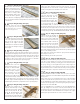
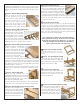
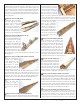
n n Step 2 - Wing Assembly (front spar)
Locate one SP1 from BP1. This
is glued in place to SP2 and
the basswood by lining up the
modified scarf joint pre-cut into
the pieces. Again, make sure
this is aligned straight with the
straight edge, and flat along
the entire length where it contacts the basswood strip.