
Fifty Six manual

Page 14 www.oldschoolmodels.com Construction Manual
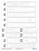
Logos, numbers, etc.
If you want to use graphics similar to the
ones we used, Old School Model Works
has teamed up with Callie Graphics as a
supplier for pre-cut vinyl. They are a very
well known provider of custom graphics
for R/C models.
We have supplied them with the artwork
needed to cut the correct size logos. You can order straight from
them, choosing the colors that work for you.
Contact Callie Graphics at this link: https://callie-graphics.com or scan
the QR code.
Note that Callie Graphics is not affiliated with Old School Model
Works, nor does Old School Model Works generate any income
from this partnership.
Attach the Control Surfaces
Now is the time to attach all the control
surfaces to the airframe, by gluing the
hinges in position with thin C/A. We've
noted suggested hinge locations for each
of the control surfaces on the plans.
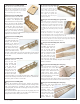
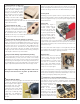
When using the CA hinges, first push a
pin through on side, at the center of the hinge as shown here. This
will keep the hinge centered as it's pushed into the surfaces. When
you've got all the hinges for a surface in place, then remove the
pins and glue the hinges.
Make sure that you attach the elevator first, then the rudder.
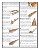
Attach wheels
Use the included 5/32” i.d. wheel collars to hold each wheel (not
included) on the axles. For a maintenance free installation, file
a small flat on the axle where the set screw of the wheel collar
touches. Also use a touch of thread-locking compound to keep the
screw from loosening over time.
Optional canopy
Included is a canopy and though it's certainly up to you if you
choose to use it, the canopy is just a defining part of the Fifty Six's'
outline, so why not use it?
The following steps will describe how to properly prepare and
attach it.
• Trim along it’s flat edge. You’ll want to trim away the excess
plastic and leave a smooth lip, roughly 3/16” wide around the
it’s perimeter.
• Place it on the wing and see if will over the wing's curvature,
starting at the leading edge. Not all canopies are exactly
identical, so a bit of trial and error is needed to get a good fit.
• If you’re going to add a pilot figure (not included), now is the
time to test-fit, then glue it in place.
• Give the canopy a quick wash in warm, soapy water.
• If you're going to tint or paint the canopy, do this on the inside
now and allow it to try.
• Use a bit of canopy glue to attach the canopy. So it doesn't
move while the glue cures, hold it in place with a bit of low-tack
masking tape.
the mounting surface for the servo's screws. If using standard size servos
for the elevator and rudder, you may need to stack the TR3's two-high
so the servos will clear the LG assembly underneath the tray.
Take a bit of time to plan things out, including how you'll run the
throttle and nose gear steering pushrods.
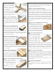
When mounting the
servos to each of the
SH's you'll need to cut
eight 3/4" lengths of the
1/4" square basswood
scrap. Make four thicker
mounting posts by
laminating two pieces
together then sand the ends flat.
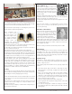
Position your aileron servo on the inside of the aileron hatch so the
servo arm output shaft is centered in the opening.
On the inside of each aileron hatch, glue one post on each side of
the servo as shown in the photo.
Note that the left hatch is a mirror image of the right hatch.
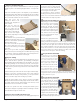
Now fit the servo hatches into position on the bottom of the wing.
Using the pre-cut holes as a guide, drill four 1/16” mounting holes
into the basswood mounting posts you just installed. Harden the
wood with a bit of thin CA and you can use the supplied 2-56 x
3/4” self tapping screws to secure the hatches in place.
Finish the layout of your radio gear by adding the receiver, flight
pack battery and the switch. We mounted the receiver to the
tray by using a bit of self-adhesive hook-and-loop (not included).
The radio's switch should be mounted to the opposite side
of the muffler (to help keep the goop out of it). Or, for an even
cleaner installation, it could be installed inside the tank/battery
compartment - hidden under the hatch - VERY NICE!
Covering
Now it is time to cover the Fifty Six. Remove the powerplant, main
gear, nosewheel assembly, pushrods, and any other components
that would get in the way of applying the covering.
Double check that all surfaces are smooth and ready to cover. Sand
as necessary, then cover the entire airframe with the covering/finish
of your choice.
Note that if you’re powering with an electric motor, you’ll need
to make a hole for the cooling air to escape the bottom of the
fuselage, near the rear.
When the covering is complete, re-attach all the components you
removed earlier in this step.