Okyanus Technology computer & Software inc Ali Rıza Gürcan Cadddesi. Alparslan İş Merkezi No: 27/15 Merter - Güngöre, İstanbul Tel: +90 (212) 481 96 22 Fax: +90 (212) 481 96 23 www.wipelot.
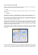
1. SETTING UP DEVICES & RF NETWORK Rest of the manual guides you through the steps necessary for setting up and configuring your Wipelot devices. Please read this manual before system setup. 1.1. Safety The device must be used solely with its original power adaptor. Please note that the adapter is 110/220V AC 1.2. Introduction Wipelot devices are based on 2.4GHZ IEEE 802.15.4 compliant RF wireless network. To form a minimal 802.15.
which listens the Location Provider System database. It interpretes fetched information and applies some business rules on it prior to UI interaction. Tags comprise a conductive security element attachment having two ends, whose electrical state will change when stretched, severed, or removed by parting the end. When the electrical state changes an alarm code will be generated and sent to receivers. This information will then be processed as explained above.
1.1. Device Definitions 1.1.1. Active RFID Reader (Wipelot Model No: FT-06DCH) Router is hierarchically the top-most Node of 802.15.4 RF Network. It forms/manages RF Network, collects all RF Network data and behaves as a gateway from RF Network to upper media. Reader device has red led and green led on itself. If green led blinks, it means that the router device tries to form Rf network. If green led lighten constantly, it means that the router device forms Rf Network succesfully.
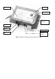
Flasher Model No Mac Address UWB Antenna Power Buzzer leds RF Antenna On- Off Buttons Figure 2: Wipelot FT-06DCH Sample Hardware Structure