2nd RS232 Serial Interface Kit P/N 80850092 Instruction Manual Segundo paquete de interfaz serial RS232 N/P 80850092 Manual de instrucciones Kit de la 2e interface série RS232 Ref. 80850092 Manuel d’instructions Satz mit 2. serieller RS232-Schnittstelle Teilenr.
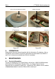
2nd RS232 Serial Interface Kit 1. EN-1 INTRODUCTION This RS232 Serial Interface Kit P/N 80850092 provides a second RS232 serial interface for the Adventurer Pro balances. Please read this manual completely before installation and operation. READ ALL SAFETY WARNINGS BEFORE INSTALLING, MAKING CONNECTIONS, OR SERVICING THE BALANCE. FAILURE TO COMPLY WITH THESE WARNINGS COULD RESULT IN PERSONAL INJURY AND/OR PROPERTY DAMAGE. RETAIN ALL INSTRUCTIONS FOR FUTURE REFERENCE. 1.
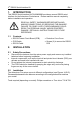
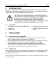
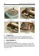
2nd RS232 Serial Interface Kit EN-2 Figure 1A. Figure 1B. Figure 1C.
2nd RS232 Serial Interface Kit EN-3 1. With power removed from the balance, remove any draft shield or draft shield glass panels, the pan, pan support and any wind ring or adapter ring (sizes and shapes vary) to fully expose the EMC plate on the top of the balance. 2. Remove the 2 screws and the EMC plate. NOTE: On some models with angular wind rings, be careful not to lose the 4 corner plastic locating pins where the EMC plate slots over.
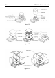
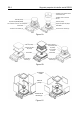
2nd RS232 Serial Interface Kit EN-4 Cone Cover (for small-frame models) Figure 2A. COM2 Cover Plate Figure 2B. nd 2 RS232 PCB Figure 2C. 3. PCB Cable Figure 2D. OPERATION Refer to the instruction manual supplied with the Adventurer Pro balance. Set up the RS232 communication and printing parameters as described in the RS232-2 and Print-2 submenus (enabled when this kit is installed). 4. MAINTENANCE 4.
Segundo paquete de interfaz serial RS232 1. ES-1 INTRODUCCIÓN Este paquete de interfaz serial RS232 N/P 80850092 proporciona una segunda interfaz serial RS232 para las balanzas Adventurer Pro. Lea completamente este manual antes de instalar y trabajar con su dispositivo. LEA TODAS LAS ADVERTENCIAS DE SEGURIDAD ANTES DE INSTALAR, HACER CONEXIONES O DAR SERVICIO A LA BALANZA. LA FALTA DE CUMPLIMIENTO DE ESTAS ADVERTENCIAS PODRÍA RESULTAR EN LESIONES PERSONALES O DAÑOS MATERIALES.
ES-2 Segundo paquete de interfaz serial RS232 Cubierta de la pantalla contra corrientes de aire Pantalla contra corrientes de aire Plato de pesaje Plato de pesaje Soporte del plato de pesaje Aro indicador de viento / Aro adaptador Soporte del plato de pesaje Placa EMC Placa EMC Tornillos de la cubierta (2) Tornillos de la cubierta (2) Figura 1A.
Segundo paquete de interfaz serial RS232 ES-3 1. Con la energía de la balanza interrumpida, retire cualquier pantalla contra corrientes de aire o paneles de cristal de pantalla contra corrientes de aire, el plato de pesaje, el soporte del plato de pesaje y cualquier aro indicador de viento o aro adaptador (los tamaños y formas varían) para exponer completamente la placa EMC en la parte superior de la balanza. 2. Retire los dos tornillos y la placa EMC.
ES-4 Segundo paquete de interfaz serial RS232 Cubierta del cono (para modelos de bastidor pequeño) Figura 2A. Placa de cubierta del COM2 Figura 2B. Cable PCB Segunda PCB RS232 Figura 2C. 3. Figura 2D. OPERACIÓN Consulte el manual de instrucciones incluido con la balanza Adventurer Pro. Configure los parámetros de comunicación e impresión del RS232 como se describe en los submenús RS232-2 y Print-2 (habilitados al instalar el paquete). 4. MANTENIMIENTO 4.
Kit de la 2e interface série RS232 1. FR-1 INTRODUCTION Ce kit d’interface série RS232, référencé 80850092 fournit une deuxième interface série RS232 pour les balances Adventurer Pro. Veuillez lire entièrement ce manuel avant l’installation et la mise en fonctionnement. VEUILLEZ LIRE TOUS LES AVERTISSEMENTS DE SÉCURITÉ AVANT D'INSTALLER, DE CONNECTER OU DE PROCÉDER À L'ENTRETIEN DE LA BALANCE. SI CES AVERTISSEMENTS NE SONT PAS RESPECTÉS, DES BLESSURES ET/OU DES DOMMAGES MATÉRIELS PEUVENT EN RÉSULTER.
2nd RS232 Serial Interface Kit FR-2 Couvercle du pare-vent Pare-vent Plateau Plateau Support plateau Virole renforcée/Anneau d'adaptation Support plateau Plaque EMC Plaque EMC 2 vis du couvercle 2 vis du couvercle Figure 1A. Plateau Plateau Support plateau Support plateau Virole renforcée Plaque EMC Plaque EMC 2 vis du couvercle 2 vis du couvercle Figure 1B. Portes en verre Plateau 2 vis du couvercle Figure 1C.
Kit de la 2e interface série RS232 FR-3 1. La balance étant déconnectée du secteur, retirez les pare-vent ou les pare-vent en verre, le plateau, le support du plateau, la virole renforcée ou l'anneau d'adaptation (les dimensions et les formes varient) afin d'exposer complètement la plaque EMC en partie supérieure de la balance. 2. Dévissez les 2 vis et la plaque EMC. REMARQUE : Certains modèles avec une virole renforcée rectangulaire comprennent 4 broches d'alignement de la plaque EMC.
2nd RS232 Serial Interface Kit FR-4 Couvercle du cône de protection en plastique (modèles à petite armature) Figure 2A. Circuit imprimé de la deuxième interface RS232 Figure 2C. 3. Plaque du couvercle COM2 Figure 2B. Câble du circuit imprimé Figure 2D. FONCTIONNEMENT Reportez-vous au manuel d'instructions fourni avec la balance Adventurer Pro.
Satz mit 2. serieller RS232-Schnittstelle 1. DE-1 EINLEITUNG Dieser serielle RS232-Schnittstellensatz, Teile-Nr. 80850092, bietet eine zweite serielle RS232-Schnittstelle für die Adventurer Pro-Waagen. Bitte lesen Sie dieses Handbuch vor der Installation und Inbetriebnahme vollständig durch. VOR DER INSTALLATION, DEM HERSTELLEN VON ANSCHLÜSSEN ODER DER DURCHFÜHRUNG VON WARTUNGSARBEITEN AN DER WAAGE MÜSSEN SIE ALLE SICHERHEITSHINWEISE LESEN.
DE-2 Satz mit 2.
Satz mit 2. serieller RS232-Schnittstelle DE-3 1. Während die Stromzufuhr zur Waage unterbrochen ist, alle installierten Zugluftschutzvorrichtungen oder Zugluftschutz-Glasplatten, die Schale, den Schalenträger und eventuell angebrachte Windringe oder Adapterringe ausbauen (Größen und Formen variieren), um die EMV-Platte oben auf der Waage vollständig freizulegen. 2. Die zwei Schrauben und die EMV-Platte ausbauen.
DE-4 Satz mit 2. serieller RS232-Schnittstelle Kegelabdeckung (für Modelle mit kleinem Rahmen) Abbildung 2A COM2-Abdeckplatte Abbildung 2B Platine 2. RS232 Abbildung 2C 3. Platinenkabel Abbildung 2D BETRIEB Beziehen Sie sich auf die mit der Adventurer Pro-Waage gelieferte Bedienungsanleitung. Richten Sie die RS232-Kommunikations- und Druckparameter gemäß der Beschreibung in den RS232-2- und Druck-2Untermenüs ein (diese sind nach Installation des Satzes aktiviert). 4. WARTUNG 4.
Kit seconda interfaccia seriale RS232 1. IT-1 INTRODUZIONE Questo kit interfaccia seriale RS232 con N/P 80850092, fornisce una seconda interfaccia seriale RS232 per le bilance Adventurer Pro. Leggere integralmente il manuale prima dell'installazione e della messa in funzione. LEGGERE TUTTE LE AVVERTENZE DI SICUREZZA PRIMA DI PROCEDERE ALL'INSTALLAZIONE, ALLA REALIZZAZIONE DEI COLLEGAMENTI ALLA MANUTENZIONE DELLA BILANCIA.
IT-2 Kit seconda interfaccia seriale RS232 Coperchio dello scudo per le correnti d'aria Scudo per correnti d'aria Piatto Piatto Supporto del piatto Anello per correnti d'aria / Anello adattatore Supporto del piatto Piastra EMC Piastra EMC Viti di copertura (2) Viti di copertura (2) Figura 1A. Piatto Piatto Supporto del piatto Supporto del piatto Anello per correnti d'aria Piastra EMC Piastra EMC Viti di copertura (2) Viti di copertura (2) Figura 1B.
Kit seconda interfaccia seriale RS232 IT-3 1. Dopo aver scollegato la bilancia dall'alimentazione, rimuovere gli scudi per correnti d'aria o i pannelli in vetro, il piatto e il suo supporto e l'anello per correnti d'aria o l'anello adattatore (dimensioni e forme variabili) per esporre completamente la piastra EMC sulla parte superiore della bilancia. 2. Rimuovere le 2 viti e la piastra EMC.
IT-4 Kit seconda interfaccia seriale RS232 Coperchio conico (per modelli con telaio piccolo) Figura 2A. Piastra di copertura COM2 Figura 2B. Secondo PCB S232 Figura 2C. 3. Cavo PCB Figura 2D. FUNZIONAMENTO Fare riferimento al manuale di istruzioni fornito con la bilancia Adventurer Pro. Impostare i parametri di comunicazione e stampa della RS232, come illustrato nei menu secondari RS232-2 e Print-2 (abilitati quando si installa il kit). 4. MANUTENZIONE 4.
Ohaus Corporation 19A Chapin Road P.O. Box 2033 Pine Brook, NJ 07058-2033, USA Tel: (973) 377-9000 Fax: (973) 944-7177 With offices worldwide / Con oficinas alrededor del mundo / Avec des bureaux dans le monde entier / Weltweite Geshäftsstellen / Con uffici in tutto il mondo. www.ohaus.com *12103998* P/N 12103998 A © Ohaus Corporation 2010, all rights reserved / todos los derechos reservados / tous droits réservés / Alle Rechte vorbehalten / tutti i diritti riservati.