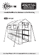
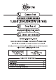
vy outgrow. ORS © Call us first CUSTOMER SERVICE NUMBER 1.855.354.GROW (4769) 6) Email us at Check our website www.ogrow.com THANK YOU FOR PURCHASING THE OGROW® GREENHOUSE Simply follow the assembly and safety instructions in this manual Should you have any questions, please call our Customer Service Department Toll-free number: 1.855.354. GROW (4769) MONDAY THURSDAY FRIDAY 9:30AM. 5:00 PM. 9:00 AM. 12:00 PM. Eastern Time. Eastern Time.
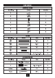
CONNECTORS Serial No. Picture Quantity TUBES Serial No. Pictures Size Quantity 465L 3 ® —_ 305'L 45 _ 175'L 47" (41.5" x 5.5") 8 OTHER PARIS Serial No.
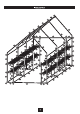
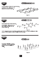
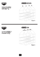
WF Step 1 Parts 12x25) 8x27 Layout the bottom Tubes of the greenhouse. Lay the tubes #24, #25 and the ground as shown in figure Figure 1 WF step 2 Ports REJECTED) 22 @ Connect the Tubes with Connectors. Connect all the tubes together with & ds ab the Connectors. Follow layout shown in figure ofp ® Figure 2 Tip: You will need to connect each item very tight repeat to tighten to each piece while connecting, to make sure the tubes are reaching until the end of connector.
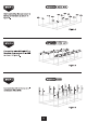
$ Start connecting the connectors to the top of the tubes as shown in figure 4. Step 4 Parts ) 5xB ) exE ) Be Pr Bose Figure 4 @ Connect the tubes #25 and #27 at the sides of connectors #B and #E as shown in figure 5.
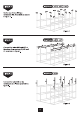
a On the top of tube #26 put connectors #B, #D and #E as shown in figure 7. step 7 Paris PECULIARITY on ods oe ge a2 ops Figure 7 @ Connect the tubes #25 and #27 at the sides of connectors #B, #D and #E as shown in figure 8. Step 8 Parts 8 L==2 2 2 $F Connect the tube #26 on the connectors at all sides as shown in figure 9.
No On the top of tube #26 put connectors #A, #C and #E as shown in figure 10. $F Connect the tubes #24, #25 and #27 with connectors #A, #C and #E as shown in figure 11. stop 10 Parts RELY ECE Figure 10 CORN 1x24) 6x25) 227) Figure 11 $F Connect the tube #28, to connectors #A, #C and #E as shown in figure 12.
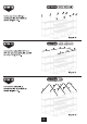
FF step 13 Parts JEGDECD the top of tube #28 put connectors #F and #G as shown in figure 13. Figure 13 Connect the tube #25 at the sides of connector #F and #G as shown in fig 14.
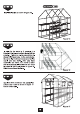
sere tc Install shelves #Z as shown in figure order for the cover to fit properly, it is 4 important that all connections be as tight as possible. Tightening all the connections will shape the Greenhouse to the correct size, cr thus enabling the Greenhouse cover to slide pd easily over the frame. After you have assembled the frame, turn frame on each side and push on all connections with force a to ensure a tight fit as shown in figure 16. TN Slide the cover over the frame.
Anchor kit assembly instructions tl Hammer the anchors into the soil, placing them on all four sides of the greenhouse. Figure 18 Connect the top end of the rope into the strap on the top of the greenhouse on all 4 sides as shown in figure 19. Figure 19 at Take the other end of the rope and pass it through the vended side of anchor as gl shown in figure.