
Quick Installation Guide

5
www.observint.com
© 2018, 2020 Observint Technologies. All rights reserved.
b. In the message bar at the bottom of the screen, click Run. Follow the on-screen instructions to
install WebComponents. When the following screen opens, click Finish.
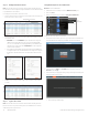
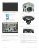
The Live View screen with the camera video image should appear.
Capture, Record, Zoom icons
Screen select tabs Logout buttonLive View image
Step 6. Insert microSD card into the camera
A microSD card installed in the provides local storage for video recordings, capture les, and log data. The
camera supports microSD cards with capacities up to 128 GB. NOTE: If the camera is not managed by an
NVR or other video management system (VMS), and doesn’t have a microSD card, video recordings, capture
les, and log data are not saved.
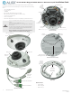
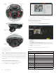
1. Remove the outer camera cover. The outer cover unsnaps from the dome cover.
2. Use a #2 Phillips screwdriver to unscrew the four captive screws that secure the dome cover to the
base assembly, and then separate it from the base assembly. At this time, do not remove the plastic
lm that protects the clear plastic dome.
Cover (captive)
screw (3)
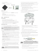
3. Insert a microSD card into the card slot as shown in the photo below. The label on the card should face
away from the mounting surface.
microSD
card slot
Back of camera base assembly
4. Push the microSD card into the slot as far as possible, and then release it. It should click into place
when fully inserted.
To remove the microSD card, push the card all the way in to release it from the connector, then
withdraw it out of the slot.
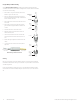
Step 7. Adjust camera pan, tilt and rotation
Adjust the camera pan, tilt and rotation to point the camera at your surveillance target. When pointing
the camera, use the Live View display on a recorder or remote login. You can also attach the BNC video
maintenance cable to the connector on the maintenance panel, and then attach it to CVBS monitor to see a
live view video from the camera.
1. While observing live video from the camera, use a #2 Phillips screwdriver to loosen the gimbal lock
screw until the gimbal is free to rotate (about three turns). The location of the lock screw is shown in
the photos on page 1 of this guide.
2. Point the camera at your surveillance target, changing the pan, tilt and rotation as needed. See below.
Always stay within the specied pan, tilt and rotation ranges of the camera.