
Quick Installation Guide

2 www.observint.com
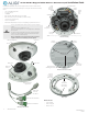
• Weatherproof Ethernet tting
• Mounting hardware - screws and wall inserts (3 each)
• This document
Dome cleaning cloth
Machine screws
Mounting hardware
Weatherproof tting
for Ethernet cable
Tools you need
To install the camera, you will need:
• If not powering with PoE, a 12 Vdc power source. See Specications for voltage and wattage
requirements.
• Phillips #2 screwdriver
• Tools and additional fasteners may be required for mounting the camera
• Ethernet, alarm, audio and power extension cables as needed for the installation.
Step 1. Install the camera
Before installation:
• Do not remove the plastic lm that protects the plastic dome.
• Make sure that the device is in good condition and all the assembly parts are included.
• Check the specication of the products for the installation environment.
• Make sure that the mounting surface is strong enough to hold 3 times the weight of the camera.
• To avoid re or shock hazard, use only UL listed power supplies. Verify that the power supply will
provide the rated voltage and wattage for the camera. See the Specications section.
Route wiring to the camera
The camera drop cable can be routed either mounting surface or out the side of the adapter plate.
NOTE
When selecting a mounting location for the camera
• Make sure that there are no reective surfaces near to the camera lens. IR light from the camera may
bounce back onto the lens causing reections.
• Determine how wiring is routed into the camera. The cable can be routed through conduit
(a threaded conduit adapter is provided), through the mounting surface and access hole in the
mounting plate, or through the side inlet.
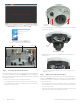
See photos above. The camera includes drop cable connectors for the following:
• Ethernet (required): The Ethernet drop cable can connect to a LAN extension cable from a switch or
Network Video Recorder. The camera can be powered across the LAN using power over Ethernet (PoE)
injection. A weatherproof Ethernet cable tting is provided. See the Specications section at the end
of this document for power requirements.
• 12 Vdc power input (optional if PoE powered, required if not PoE): If powering the camera with a
long power extension cable, refer to the tables at the end of this guide for wire gauge requirements.
Voltage input at the camera can be within the range 12 Vdc ± 25%.
• Alarm IN / OUT, Audio IN / OUT (optional): Connect these leads to auxiliary devices as needed. The
camera supports one alarm input, one alarm output, one audio input and one audio output. Terminals
on the drop cable are screw down connectors.
• Ground: A ground terminal is provided near to where the crop cable attaches to the camera. Follow
local electrical codes for grounding procedures.
1. Route a LAN extension cable from a network switch or Network Video Recorder to where the camera
will be installed.
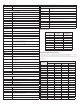
2. If the camera is not powered using PoE, route 12 Vdc power cables from an adequate power source
to the location where the camera will be installed. Refer to the Specications section for power
requirements. Also, for long line power leads, refer to the Wire Gauge Standards and 12 Vdc Wire
Gauge and Transmission Distance tables at the end of this document. Voltage input at the camera can
be within the range 12 Vdc ± 25%.
CAUTION
Do not apply power to the camera at this time. Before applying power to the camera, ensure
that the polarity is correct. An incorrect connection may cause a malfunction and can damage
the camera.
3. Install an alarm input and an alarm output devices as needed, and then route wires from them to
where the camera will be installed. Alarm terminations for one input (NO or NC) and one output alarm
device (DC or AC) are screw-down connectors that accommodate bare wires.
4. Install audio input and out devices as needed, and then route cables from them to where the camera
will be installed. Audio terminations in the camera are 3.5 mm plugs.
5. Determine the method for mounting the camera considering:
— The camera lens adjustments allow a pan of ±30˚, tilt of 0˚ ~ 75˚, and rotation of 0˚ ~ 360˚.
When mounting the camera, point it at your surveillance target.
— Where the camera drop cables will connect to the interface cabling.
— The length of the camera drop cable.
6. Determine the best mounting hardware (screws, wall inserts) for the surface on which you will mount
the camera. The screws and wall inserts are adequate for many types of surfaces.
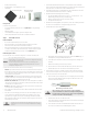
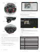
7. Install the adapter plate on the mounting surface:
Mounting
surface
Knockout for
cable routing
Orientation mark
Adapter plate
a. Place the adapter plate on the mounting surface with the orientation mark (Front triangle, see
the drawing above) pointing toward the desired eld of view.
b. Use the adapter plate to mark the hole locations on the mounting surface for mounting screws
and cable(s).
c. Drill holes for the mounting screws and crop cable, as needed.
d. If the drop cable will be routed out the side of the adapter plate, remove the cable knockout.
e. Attach the adapter plate to the surface with the screws and wall inserts, if needed.
8. Route the Ethernet, power, alarm I / O, and audio out extension cables from the camera mounting
location to the devices they will connect to. Do not apply power to any extension cables at this time.
9. Connect the extension cables to the camera drop cables.
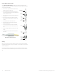
a. If the location where you are installing the camera is excessively dusty or has potential for high
moisture levels, install the Weatherproof Ethernet Fitting on the LAN extension cable. See the
instructions at the end of this document.
Network drop cable
from camera
Network cable from
router or switchEthernet Fitting installed
Ethernet Fitting assembled and connected
WARNING
!
Failure of the Ethernet connector due to moisture or another contaminant is
considered an installation error, which voids the warranty. If installing this camera
in a location such as an overhang, shop, garage, kitchen, etc. where high humidity
or dust is present, seal these connections adequately.
b. Attach the Ethernet drop cable to the LAN extension cable.
c. Connect the ground cable to the ground terminal on the back of the camera base assembly. This
location is shown in the photo on page 1.
d. Connect the audio extension cables to the Audio IN and OUT terminals on the drop cable. Seal
these connectors as needed to prevent contamination by dust or moisture.
© 2018, 2020 Observint Technologies. All rights reserved.