
Datasheet

UBA2028 All information provided in this document is subject to legal disclaimers. © NXP B.V. 2010. All rights reserved.
Product data sheet Rev. 02 — 19 July 2010 5 of 23
NXP Semiconductors
UBA2028
600 V dimmable power IC for compact fluorescent lamps
7. Pinning information
7.1 Pinning
7.2 Pin description
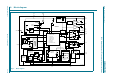
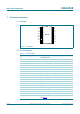
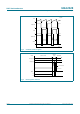
Fig 2. Pin diagram
UBA2028
HV SL
FS SH
FS
GND PCS
GLI
ACM V
DD
LVS GLO
VREF GND
CSP IREF
CSN CF
CT CSW
014aaa904
1
2
3
4
5
6
7
8
9
10
12
11
14
13
16
15
18
17
20
19
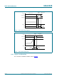
Table 3. Pin description
Symbol Pin Description
HV 1 high voltage input
FS 2 floating supply voltage; supply for high-side switch
FS 3 floating supply voltage; supply for high-side switch
GND 4 ground
ACM 5 capacitive mode input
LVS 6 lamp voltage sensor input
VREF 7 reference voltage output
CSP 8 positive input for the average current sensor
CSN 9 negative input for the average current sensor
CT 10 preheat timer output
CSW 11 input of voltage controlled oscillator
CF 12 voltage controlled oscillator output
IREF 13 internal reference current input
GND 14 ground
GLO 15 gate output for the low-side switch, must be wired to pin 18
V
DD
16 low voltage supply
PCS 17 preheat current sensor input
GLI 18 gate input for the low-side switch, must be wired to pin 15.
SH 19 source for the high-side switch
SL 20 source low-side switch, connected to PGND via a resistor;
see Figure 7